

Paper Menu >>
Journal Menu >>
 Open Journal of Applied Sciences, 2012, 2, 319-325 doi:10.4236/ojapps.2012.24046 Published Online December 2012 (http://www.SciRP.org/journal/ojapps) A 2D Finite Element Study on the Flow Pattern and Temperature Distribution for an I sothermal Spherical Furnace with the Aperture Sudhakar Matle, Subbiah Sundar Mathematics, IIT Madras, Chennai, India Email: [email protected]m, [email protected] Received October 11, 2012; revised November 12, 2012; accepted November 21, 2012 ABSTRACT Calibration of radiation thermometers is one of the important research activities in the field of metrology. Many re- searchers in recent times have conducted numerical simulations on the calibration furnace to understand and overcome the experiment limitations. This paper presents a 2D numerical free convective study on the calibration furnace with the aperture using finite element method. The focused issues here are: aspect ratio effect on the flow pattern and tempera- ture fields, heat transfer mechanism in the aperture zone as well as in hump regime. It is concluded that flow and tem- perature fields follow the same behavior in the hump regime as well as in the aperture zone. Also, it concluded that penetrative convection is more dominant for the enclosure of high aspect ratio. Keywords: Calibration Furnace; Thermal Penetration; Rayleigh Number; Aspect Ratio 1. Introduction Temperature measurement of the very hot objects by means of contact thermocouple is not always handy. For this purpose, radiation thermometer is used to measure temperature in terms of radiation emitted by the hot ob- ject. Radiation thermometer is a temperature measure- ment instrument and measures temperature of the very hot object from a distance. For accuracy of the instru- ment, it must be calibrated. Calibration is an act of ad- justing instrument by comparison against any standard surface. The Saturn (a hollow spherical cavity) is one of such standards used in radiation thermometer calibration [1]. For details on calibration furnace and the finite ele- ment modeling to study experiment limitations, one can refer authors’ previous work [2]. Many research efforts have been done finite element modeling [3,4] of calibration furnaces, industrial fur- naces, heated spheres [5,6] and solar cavity receivers for quality equipment. Recently, Oluwole et al. [7] studied the flow patterns in two salt bath furnaces using finite element analysis. The implications of the heat flows on long term stability of furnace performance were evalu- ated. Khoei et al. [8] developed a finite element model that is employed to simulate the furnace rotation and analyze energy flows inside the furnace. Also, finite element, stream function vorticity solutions for steady state incompressible Navier Stokes equations are derived in papers [9,10]. Natural convection in fluid filled enclosures [11,12] with heating bottom and sides [13] have been studied extensively. Sarris et al. [14] studied numerically natural convection in a rectangular enclosure with heating from the top wall with all others insulated by varying Rayleigh number from 102 to 108 and the aspect ratio from 0.5 to 2. Recently, Hartlep et al. [15] performed simulations of Rayleigh-Benaurd convection in a large box of aspect ratio 10 over a range of Rayleigh and Prandtl numbers provide important insight into the choice of the aspect ratio. In another study, Lee et al. [16] stressed the need for very large aspect ratio domains by studying the natu- ral convection in a horizontal fluid layer with a periodic array of internal square cylinders. Finite element mesh is a part of numerical simulation study. Sensitivity analysis for parameter dependent opti- mization problems is an active area of research in the context of solution of partial differential equations. Beck- er and Vexler [17,18] investigated sensitivity of the mesh based on relative condition numbers which describe the influence of small changes in measurements on the value of interest functional. This paper addresses a 2D numerical free convective study on the calibration furnace with the aperture. In the next section, the 2D problem, governing equations and the corresponding boundary conditions are systematically discussed. In Section 3, mathematical formulation of 2D Copyright © 2012 SciRes. OJAppS 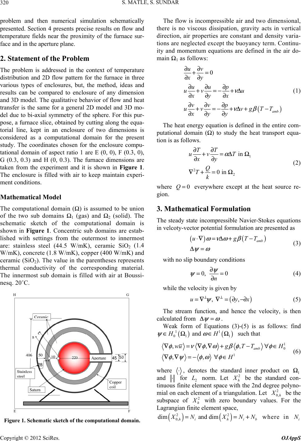 S. MATLE, S. SUNDAR 320 problem and then numerical simulation schematically presented. Section 4 presents precise results on flow and temperature fields near the proximity of the furnace sur- face and in the aperture plane. 2. Statement of the Problem The problem is addressed in the context of temperature distribution and 2D flow pattern for the furnace in three various types of enclosures, but, the method, ideas and results can be compared to enclosure of any dimension and 3D model. The qualitative behavior of flow and heat transfer is the same for a general 2D model and 3D mo- del due to bi-axial symmetry of the sphere. For this pur- pose, a furnace slice, obtained by cutting along the equa- torial line, kept in an enclosure of two dimensions is considered as a computational domain for the present study. The coordinates chosen for the enclosure compu- tational domain of aspect ratio 1 are E (0, 0), F (0.3, 0), G (0.3, 0.3) and H (0, 0.3). The furnace dimensions are taken from the experiment and it is shown in Figure 1. The enclosure is filled with air to keep maintain experi- ment conditions. Mathematical Model The computational domain (Ω) is assumed to be union of the two sub domains Ω1 (gas) and Ω2 (solid). The schematic sketch of the computational domain is shown in Figure 1. Concentric sub domains are estab- lished with settings from the outermost to innermost are: stainless steel (44.5 W/mK), ceramic SiO2 (1.4 W/mK), concrete (1.8 W/mK), copper (400 W/mK) and ceramic (SiO2). The value in the parentheses represents thermal conductivity of the corresponding material. The innermost sub domain is filled with air at Boussi- nesq. 20˚C. H G E F Figure 1. Schematic sketch of the computational domain. The flow is incompressible air and two dimensional, there is no viscous dissipation, gravity acts in vertical direction, air properties are constant and density varia- tions are neglected except the buoyancy term. Continu- ity and momentum equations are defined in the air do- main Ω1 as follows: () 0 amb uv xy uu p uv u xy x vvp uv vgTT xy y ν νβ ∂∂ += ∂∂ ∂∂ ∂ +=−+Δ ∂∂ ∂ ∂∂ ∂ +=−+Δ+ − ∂∂ ∂ (1) The heat energy equation is defined in the entire com- putational domain (Ω) to study the heat transport equa- tion is as follows. 1 2 2 in 0 in TT uv T xy Q Tk α ∂∂ +=ΔΩ ∂∂ ∇+= Ω (2) where everywhere except at the heat source re- gion. 0Q= 3. Mathematical Formulation The steady state incompressible Navier-Stokes equations in velcoty-vector potential formulation are presented as () () amb ugT ωνωβ ψω ⋅∇= Δ+− Δ= T (3) with no slip boundary conditions 0, 0 n ψ ψ ∂ = ∂= ) yx (4) while the velocity is given by ( , ,u ψ ⊥⊥ =∇∇= ∂−∂ (5) The stream function, and hence the velocity, is then calculated from ψ ω Δ=. Weak form of Equations (3)-(5) is as follows: find such that () () 1 01 1 and HH ψω ∈Ω ∈Ω 1 1 0 1 ,,, ,, amb wugT TH H φνφωβφ φ φψφω φ ∇=∇∇+ −∀∈ ∇∇ =−∀∈ (6) where ⋅, denotes the standard inner product on 1 and Ω ⋅ for 2 norm. Let L2 h X be the standard con- tinuous finite element space with the 2nd degree polyno- mial on each element of a triangulation. Let 2 0,h X be the subspace of 2 h X with zero boundary values. For the Lagrangian finite element space, () () 22 0, dim and dim hih ib X NXN==N+ where in i N Copyright © 2012 SciRes. OJAppS 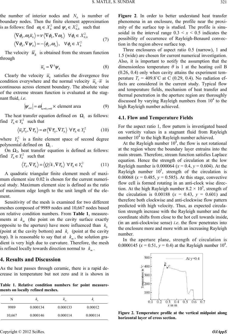 S. MATLE, S. SUNDAR 321 the number of interior nodes ando N ent b is number f boundary nodes. Then the finite elem approximation is as follows: find 22 0, and hhh h X X ωψ ∈∈ such that 2 0, ,, hhh h uX φω ∇ Figure 2. In teand hsfer phen an enclure, tile near toxi- mie su is ste pronu- assumption that the di is investigated based from Rayleigh hieved. place eq order to betr underst 2 ,,, h hh hhhh hh X ν φωφ φψφω φ =∇∇∀∈ ∇∇ =−∀∈(7) The velocity h u is obtained from the stream thro function ugh hh u ψ ⊥ =∇ (8) Clearly the velocity h u sat co t isfies the divergence free ndition everywhere andhe normal velocity h un⋅ is continuous across element boundary. The absolute value of the extreme stream function is evaluated at the stag- nant fluid, i.e. 0, 0element area ext uv ψω == =× (9) The heat transfer equation defined on fin Ω1 as follows: d hh TY∈ such that 2 2 , h h τα ∇= , hhhh h uTT Y τ τ ∇∇ ∀∈ (10) where is a finite element space of sec 2 h Y ia ond degree polynoml defined on 1 Ω. On Ω2, heat transfer equation is defined as follows: fin 2 TY∈ d hh such that 2 , hh τ ∇= , h hh TQk Y ττ ∇ ∀∈ (11) A quadratic triangular finite element m mu ic, there is a rapid de- ents on locally refined meshes. esh of maxi- m element size 0.02 is chosen for the current numeri- cal study. Maximum element size is defined as the ratio of maximum edge length to the unit length of the ele- ment. Sensitivity of the mesh is examined for two different meshes composed of 9989 nodes and 10,667 nodes based on relative condition numbers. From Table 1, measure- ments at m k (the point on the cavity surface exactly opposite to the aperture) have more influenced than b k (point at the cavity bottom) and t k (point at the cavity top). It is reasonable to say that at m k, the solution gra- dient is very high due to curvature. Therefore, the mesh is refined locally towards direction normal to m k. 4. Results and Discussion As the heat passes through ceram crease in temperature but not zero and it is shown in Table 1. Relative condition numbers for point measure- m N b k m k t k 9989 0.000 0.0001 0.00012 13433 eat tran nomena i ty of th os rface top he prof udied. Th he pr file is si soidal in the interval range 0.3 < x < 0.5 indicates the possibility of occurrence of Rayleigh-Benaurd convec- tion in the region above surface top. Three enclosures of aspect ratio 0.5 (narrow), 1 and 1.5 (wide) are chosen for current numerical investigation. Also, it is important to notify the mensionless temperature θ is 1 at the heating coil B (0.26, 0.4) only when cavity attains the experiment tem- perature Ts = 409.8˚C at C (0.29, 0.4). No radiation ef- fects are considered in the current study. Typical flow and temperature fields, mechanism of heat transfer and thermal penetration in the aperture region are thoroughly discussed by varying Rayleigh numbers from 104 to the high Rayleigh number achieved. 4.1. Flow and Temperature Fields For the aspect ratio 1, flow pattern on vorticity values in a stagnant fluid number 104 to the high Rayleigh number ac At the Rayleigh number 104, the flow is not rotational at the region where the boundary layer entrains into the main stream. Therefore, stream function satisfies La uation. Hence the strength of circulation at the low Rayleigh number is 0.000064 (x = 0.4, y = 0.604). At the Rayleigh number 105, strength of the circulation is 0.00068 (x = 0.485, y = 0.585). At this stage, convective flow cell is formed rotating in an anti-clock wise direc- tion. At the high Rayleigh number 8.2 × 10⁵, strength of the circulation is 0.00188 (x = 0.43, y = 0.601) and therefore both clockwise and anti-clockwise flow pattern predicted with high velocity. Thus, as expected circula- tion strength increase with the Rayleigh number and the coordinate shifts from close to the hot cell towards inside, (in an anti-clockwise sense) i.e. the flow penetrates into the enclosure more and more with an increasing Rayleigh number. In the aperture plane, strength of circulation is 0.0000145 (x = 0.51, y = 0.4) at the Rayleigh number 104. x in m Figure 2. Temperature profile at the vertical midpoint along horizontal layer of cross sec tion. 10,667 0.000146 0.000114 0.000114 Copyright © 2012 SciRes. OJAppS 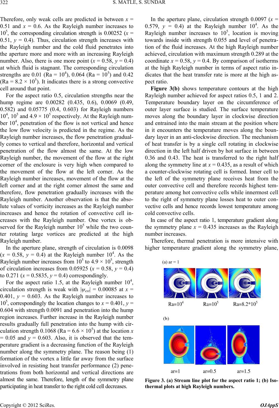 S. MATLE, S. SUNDAR 322 Therefore, only weak celredicted in between x = n strength is 0.00252 (x = .4, 0.603) for Rayleigh numbers 10 creases from 105 to 4.9 × 10⁵, strength of eases to 10 g to e boundary layer on the circumference of ou ls are p 0.51 and x = 0.6. As the Rayleigh number increases to 105, the corresponding circulatio 0.51, y = 0.4). Thus, circulation strength increases with the Rayleigh number and the cold fluid penetrates into the aperture more and more with an increasing Rayleigh number. Also, there is one more point (x = 0.58, y = 0.4) at which fluid is stagnant. The corresponding circulation strengths are 0.01 (Ra = 104), 0.064 (Ra = 105) and 0.42 (Ra = 8.2 × 10⁵). It indicates there is a strong convective cell around that point. For the aspect ratio 0.5, circulation strengths near the hump regime are 0.00282 (0.435, 0.6), 0.0069 (0.49, 0.582) and 0.05775 (0 4, 105 and 4.9 × 10⁵ respectively. At the Rayleigh num- ber 104, penetration of the flow is not vertical and hence the low flow velocity is predicted in the regime. As the Rayleigh number increases, the flow penetration gradual- ly comes to vertical and therefore, horizontal and vertical penetration of the flow almost the same. At the low Rayleigh number, the movement of the flow at the right corner of the enclosure is very high when compared to the movement of the flow at the left corner. As the Rayleigh number increases, movement of the flow at the left corner and at the right corner almost the same and therefore, flow penetration gradually increases with the Rayleigh number. Another observation is that the abso- lute values of vorticity increases as the Rayleigh number increases and hence the rotation of convective cell in- creases with the Rayleigh number. One vortex is ob- served for the Rayleigh number 105 while the two coun- ter rotating large vortices are predicted at the high Rayleigh number. In the aperture plane, strength of circulation is 0.0098 (x = 0.58, y = 0.4) at the Rayleigh number 104. As the Rayleigh number in circulation increases from 0.05925 (x = 0.58, y = 0.4) to 0.271 (x = 0.5835, y = 0.4) correspondingly. For the aspect ratio 1.5, at the Rayleigh number 104, circulation strength is weak with |ψext| = 0.00085 at x = 0.401, y = 0.603. As the Rayleigh number incr 5, correspondingly the location changes to x = 0.401, y = 0.604 with strength 0.0091 and penetration into the hump region increases. Further increase in the Rayleigh number results gradually full penetration into the hump with cir- culation strength 0.1068 (Ra = 6.6 × 10⁵) at the location x = 0.05 and y = 0.603. Also, it is observed that the tem- perature gradient is a decreasing function of the Rayleigh number along the symmetry plane. The reason being (1) formation of the vortex a little far away from the surface involved in resisting heat transfer performance (2) pene- trations from both horizontal and vertical directions are almost the same. Therefore, length of the symmetry plane participating in heat transfer to the right cold cell decreases. In the aperture plane, circulation strength 0.0097 (x = 0.579, y = 0.4) at the Rayleigh number 104. As the Rayleigh number increases to 105, location is movin wards inside with strength 0.055 and level of penetra- tion of the fluid increases. At the high Rayleigh number achieved, circulation with maximum strength 0.289 at the coordinate x = 0.58, y = 0.4. By comparison of isotherms at the high Rayleigh number in terms of aspect ratio in- dicates that the heat transfer rate is more at the high as- pect ratio. Figure 3(b) shows temperature contours at the high Rayleigh number achieved for aspect ratios 0.5, 1 and 2. Temperatur ter layer surface is studied. The surface temperature moves along the boundary layer in clockwise direction and entrained into the main stream at the position where in it encounters the temperature moves along the boun- dary layer in an anti-clockwise direction. The mechanism of heat transfer is by a single cell rotating in clockwise direction in the left half driven by hot surface in between 0.36 and 0.43. The heat is transferred to the right half along the symmetry line at x = 0.435, as a result of which a counter-clockwise rotating cell is formed. Inner cell to the left of the symmetry plane receives heat from the outer convective cell and therefore records highest tem- perature among hot convective cells while innermost cell to the right of symmetry plane losses heat to outer con- vective cells and hence records lowest temperature among cold convective cells. In case of the aspect ratio 1, temperature gradient along the symmetry plane x = 0.435 increases as the Rayleigh number increases. Therefore, thermal penetration is more intensive with higher temperature gradient along the symmetry plane, (a) ar = 1 Figure 3. (a) Stream line plot for the aspect ratio 1; (b) Iso- thermal plots at high Rayleigh numbers. Copyright © 2012 SciRes. OJAppS 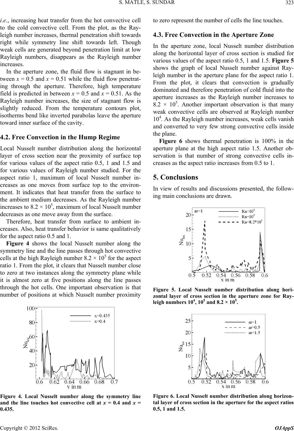 S. MATLE, S. SUNDAR 323 i.e., increasing heat transfer from the hot convective cell to the cold convective cell. From the plot, as the Ray- leigh number increases, thermal penetration shift towards right while symmetry line shift towards left. Though weak cells are generated beyond penetration limit at low Rayleigh numbers, disappears as the Rayleigh number increases. In the aperture zone, the fluid flow is stagnant in be- tween x = 0.5 and x = 0.51 while the fluid flow penetrat- ing through the aperture. Therefore, high temperature field is predicted in between x = 0.5 and x = 0.51. As the Rayleigh number increases, the size of stagnant flow is slightly reduced. From the temperature contours plot, isotherms bend like inverted parabolas leave the aperture toward inner surface of the cavity. .2 × 105 for the aspect r close while 4.2. Free Convection in the Hump Regime Local Nusselt number distribution along the horizontal layer of cross section near the proximity of surface top for various values of the aspect ratio 0.5, 1 and 1.5 and for various values of Rayleigh number studied. For the aspect ratio 1, maximum of local Nusselt number in- creases as one moves from surface top to the environ- ment. It indicates that heat transfer from the surface to the ambient medium decreases. As the Rayleigh number increases to 8.2 × 10⁵, maximum of local Nusselt number decreases as one move away from the surface. Therefore, heat transfer from surface to ambient in- creases. Also, heat transfer behavior is same qualitatively for the aspect ratio 0.5 and 1. Figure 4 shows the local Nusselt number along the symmetry line and the line passes through hot convective cells at the high Rayleigh number 8 ratio 1. From the plot, it clears that Nusselt numbe to zero at two instances along the symmetry plane it is almost zero at five positions along the line passes through the hot cells. One important observation is that number of positions at which Nusselt number proximity Figure 4. Local Nusselt number along the symmetry line and the line touches hot convective cell at x = 0.4 and x = 0.435. to zero represent the number of cells the line touches. 4.3. Free Convection in the Aperture Zone In the aperture zone, local Nusselt number distribution along the horizontal layer of cross section is studied for various values of the aspect ratio 0.5, 1 and 1.5. Figure 5 shows the graph of local Nusselt number against Ray- leigh number in the aperture plane for the aspect ratio 1. From the plot, it clears that convection is gradually dominated and therefore penetration of cold fluid into the aperture increases as the Rayleigh number increases to 8.2 × 10⁵. Another important observation is that many weak convective cells are observed at Rayleigh number 104. As the Rayleigh number increases, weak cells vanish and converted to very few strong convective cells inside plane at the high aspect ratio 1.5. Another ob- in- creases as the aspect ratio increases from 0.5 to 1. the plane. Figure 6 shows thermal penetration is 100% in the aperture servation is that number of strong convective cells 5. Conclusions In view of results and discussions presented, the follow- ing main conclusions are drawn. Figure 5. Local Nusselt number distribution along hori- zontal layer of cross section in the aperture zone for Ray- leigh numbers 104, 105 and 8.2 × 10⁵. Figure 6. Local Nusselt number distribution along horizon- tal layer of cross section in the aperture for the aspect ratios 0.5, 1 and 1.5. Copyright © 2012 SciRes. OJAppS 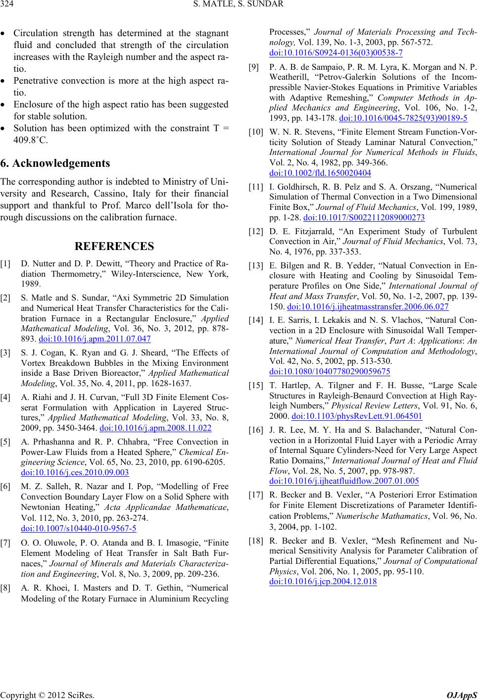 S. MATLE, S. SUNDAR Copyright © 2012 SciRes. OJAppS 324 • Circulation strength has determined at the stagnant fluid and concluded that strength of the circulation increases with the Rayleigh number and the aspect ra- tio. • Penetrative convection is more at the high aspect ra- tio. • Enclosure of the high aspect ratio has been suggested for stable solution. • Solution has been optimized with the constraint T = 409.8˚C. 6. Acknowled ge ments The corre spond ing autho r is indebted to Ministry of Uni- versity and Research, Cassino, Italy for their financial support and thankful to Prof. Marco dell’Isola for tho- rough discus sions on the calibration furnace. REFERENCES [1] D. Nutter and D. P. Dewitt, “Theory and Practice of Ra- diation Thermometry,” Wiley-Intersci en ce, New York, 1989. [2] S. Matle and S. Sundar, “Axi Symmetric 2D Simulation and Numerical He at Transfer C haracteristics for the Cali- bration Furnace in a Rectangular Enclosure,” Applied Mathematical Modeling, Vol. 36, No. 3, 2012, pp. 878- 893. doi:10.1016/j.apm.2011.07.047 [3] S. J. Cogan, K. Ryan and G. J. Sheard, “The Effects of Vortex Breakdown Bubbles in the Mixing Environment inside a Base Driven Bioreactor,” Applied Mathematical Modeling, Vol. 35, No. 4, 2011, pp. 1628-1637. [4] A. Riahi and J. H. Curvan, “Full 3D Finite Element Cos- serat Formulation with Application in Layered Struc- tures,” Applied Mathematical Modeling, Vol. 33, No. 8, 2009, pp. 3450-3464. doi : 10.1016/j.apm.2008.11.022 [5] A. Prhashanna and R. P. Chhabra, “Free Convection in Power-La w Fluids from a Heated Sphere,” Chemical En- gin eering Science, Vol. 65, No. 23, 2010, p p. 6190-6205 . doi:10.1016 / j . c es . 2010. 09.003 [6] M. Z. Salleh, R. Nazar and I. Pop, “Modelling of Free Convection Boundary Layer Flow on a Solid Sphere with Newtonian Heating,” Acta Applicandae Mathematicae, Vol. 112, No. 3, 2010, pp. 263-274. doi:10.1007 / s10440-010-9567-5 [7] O. O. Oluwole, P. O. Atanda and B. I. Imas ogie, “Finite Element Modeling of Heat Transfer in Salt Bath Fur- naces,” Journal of Minerals and Materials Characteriza- tion and Engineering, Vol. 8, No. 3, 2009, pp. 209-236. [8] A. R. Khoei, I. Masters and D. T. Gethin, “Numerical Modeling of the Rotary Furnace in Aluminium Recycling Processes,” Journal of Materials Processing and Tech- nology, Vol. 139, No. 1-3, 20 03, pp. 567-572. doi:10.1016 / S 0924-0136(03)00538-7 [9] P. A. B. d e Sampaio , P. R. M. Lyr a, K . Morgan and N. P. Weatherill , “Petr o v-Galerkin Solutions of the Incom- pressible Navier-Stokes Equations in Primitive Variables with Adaptive Remeshing,” Computer Methods in Ap- plied Mechanics and Engineering, Vol . 106, No. 1-2, 1993, pp. 143-178. doi:10.1016/0045-7825(93)90 18 9-5 [10] W. N. R. Stevens, “Fini te Element Stream Function-Vor- ticity Solution of Steady Laminar Natural Convection,” International Journal for Numerical Methods in Fluids, Vol. 2, No. 4, 1982, pp. 349-366. doi:10.1002 / fld.16 500204 04 [11] I. Goldhirsch, R. B. Pelz and S. A. Orszang, “Numerical Simulation of Thermal Con vection in a Two D imensional Finite Box,” Journal of Fluid Mechanics, Vol . 199, 1989, pp. 1-28. doi:10.1017/S0022112089000273 [12] D. E. Fitzjarrald, “An Experiment Study of Turbulent Convectio n in Air,” Jou rnal of Fluid Mechanics, Vol. 73, No. 4, 1976, pp. 337-353. [13] E. Bilgen and R. B. Yedder, “Natual Convection in En- closure with Heating and Cooling by Sinusoidal Tem- perature Profiles on One Side, ” International Journal of Heat and Mass Transfer, Vol. 50, No. 1-2, 2007, pp. 139- 150. doi:10.1016/j.ijheatmasstransfer.2006.06.027 [14] I. E. Sarris, I. Lekakis and N. S. Vlachos, “Natural Con- vection in a 2D Enclosure with Sinusoidal Wall Temper- ature,” Numerical Heat Transfer, Part A: Applications: An International Journal of Computation and Methodology, Vol. 42 , No. 5, 2002, pp. 513-530. doi:10.1080 / 104077 80290059675 [15] T. Hartlep, A. Tilgner and F. H. Busse, “Large Scale Stru ctu r es in Rayleigh-Benaurd Convection at High Ray- leigh Numbers,” Ph ysical Review Letters, Vol. 91, No. 6, 2000. doi:10.1103/physRevLett.91.064501 [16] J. R. Lee, M. Y. Ha and S. Balachander, “Natural Con- vection in a Horiz onta l Flui d Layer with a Periodic Array of Internal Square Cylinders -Need for Very Large Aspect Ratio Domains,” International Journal of Heat and Fluid Flow, Vol. 28, No. 5, 2007, pp. 978-987. doi:10.1016/j.ijheatfluidflow.2007.01.005 [17] R. Becker and B. Vexler, “A Posteriori Error Estimation for Finite Element Discretizations of Parameter Identifi- cation Problems,” Nu m erische Mathamatics, Vol. 96, No. 3, 2004, pp . 1-102. [18] R. Becker and B. Vexler, “Mesh Refinement and Nu- merical Sensitivity Analysis for Parameter Calibration of Partial Differential Equations,” Journal of Computational Physics, Vol. 206, No. 1, 2005, pp. 95-110. doi:10.1016 / j . jcp.20 04.12 .0 18  S. MATLE, S. SUNDAR 325 Nomenclature , x y Cartesian coordinates ,uv Velocity vectors p Pressure T Solution temperature, [˚C] Ra Rayleigh number g Acceleration due to gravity, 2 ms κ Thermal conductivity [ ] WmK Pr Prandtl number = 0.71 Heat source Q3 Wm Greeks α Thermal diffusivity, 2 ms β Coefficient of thermal expansion, [ ] 1 K p C Specific heat capacity at constant pressure, [ ] J KgK ρ Density of air, 3 kg m ε Emissivity of the cavity=0.98 Dimensionless temperature θ = () ref TT T−Δ Copyright © 2012 SciRes. OJAppS |