

Paper Menu >>
Journal Menu >>
 Journal of Electromagnetic Analysis and Applications, 2012, 4, 504-512 http://dx.doi.org/10.4236/jemaa.2012.412071 Published Online December 2012 (http://www.SciRP.org/journal/jemaa) Simulation, Fabrication and Tests of a GPS Antenna on the Roof-Top of an Automobile Margarita Tecpoyotl-Torres, Jose G. Vera-Dimas, Gustavo Urquiza Beltrán, L. Cisneros-Villalobos, Vladymyr Grimalsky, Svetlana V. Koshevaya Centro de Investigación en Ingeniería y Ciencias Aplicadas, Universidad Autónoma del Estado de Morelos, Cuernavaca, Mexico. Email: [email protected] Received October 4th, 2012; revised November 6th, 2012; accepted November 16th, 2012 ABSTRACT It is very important for the car users to have several communication systems and many antennas, which respond to the demands of aesthetics and efficiency. In this case, it is necessary to consider different types of materials and geometries. Among the automobile systems, the navigation systems are found, which are formed by a Global Position System (GPS), with a pre-charged base of maps and highways in order to locate the vehicle. For the reception of the GPS signals, cir- cularly polarized patch antennas are used, which must be designed to operate at 1.57 GHz. This work is focused on the analysis of a circular antenna performance, designed for GPS, by means of the simulation of the following cases: an- tenna without radome, antenna with acrylic radome, and, finally, antenna on the roof of an automobile, considering the effect of the complete chassis. A Basic, a Simplified and a More Simplified Advanced Car Models (BCM, SACM, and MSACM) were used in order to analyze the chassis shape. The simulations were carried out with the software FEKO. The fabrication and experimental and practical tests are also presented. Keywords: Car Model; Circular Polarization; Patch Antennas; Rogers RT/Duroid 5880 1. Introduction The evolution of the automobiles has corresponded to several demands of the users. Especially in wireless com- munication systems, the necessity of aesthetics and effi- ciency has determined several proposals of antenna mo- dels designed considering different types of materials and geometries. The location of the antennas constitutes also a very interesting analysis problem [1,2]. The automotive sector has shown its interest in the de- velopment and implementation of navigation systems, which are composed by a GPS and a pre-charged base of maps and highways in order to locate the vehicles [3]. With the increase in automobile usage, accurately deter- mining automobile location has become one of the grow- ing priorities. The main advantages of the navigation sys- tems are reduction in the time of journey, in consumption of combustible, and in the emission of contaminant gases [4]. Other application of the GPS technology is automatic location of vehicles (AVL) [5,6], as the medium to de- termine the geographic position of the vehicle and to transmit this information to a point where it can be used and exploited. This tool is extremely useful to the man- agement of fleets of service vehicles, emergencies, con- struction, public transportation, recovery stolen vehicles, and public security [7]. The GPS antenna design has received a special atten- tion. Toyota Central R & D Laboratories of Japan has de- veloped an antenna for installation on the roof of auto- mobile [2]. They have used a dual-feed, stub loaded sin- gle patch to achieve circular polarization at the two fre- quencies of the satellite. On the other hand, the antenna radomes have received a special attention, not only on the materials used, but also in shapes. Motorola, one of the leading manufactur- ers of automotive GPS systems, recommends the place- ment of the GPS antennas at the roof, roofline or trunk [8]. Additionally, several companies are dedicated to com- mercialize navigation systems for vehicles that do not account with the original device [9]. The antennas con- tribute greatly to the total operation of the navigation systems, and they can be designed in accordance to the aesthetics and the requirements of the vehicle, in order to obtain prototypes totally personalized. Antennas, commonly used for circular polarization, are based on corner-truncated square microstrips [10], and on square or circular patches with one or two feed points [2]. A circular polarization can, also, be obtained from a single-point square or a circular patch. Copyright © 2012 SciRes. JEMAA 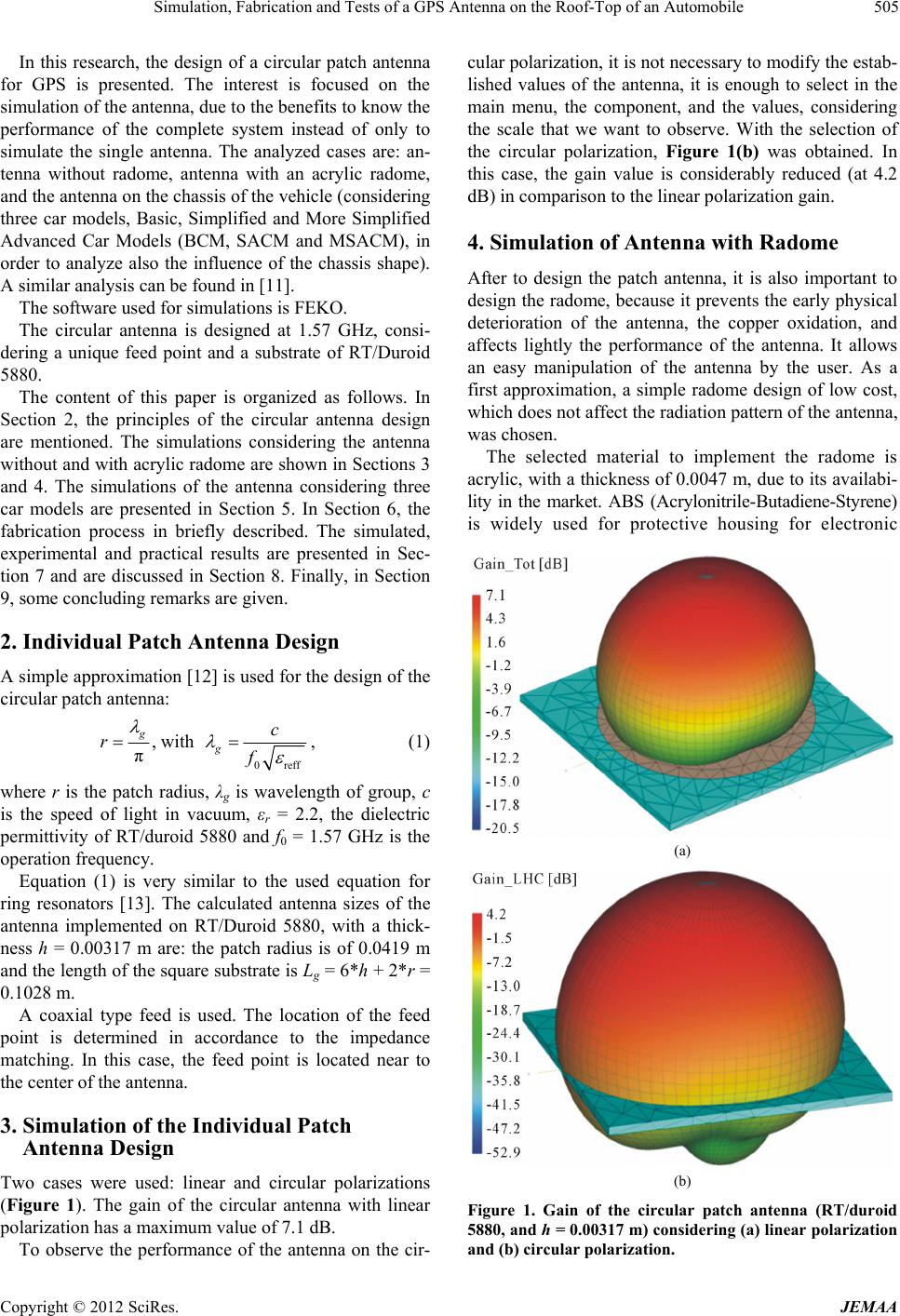 Simulation, Fabrication and Tests of a GPS Antenna on the Roof-Top of an Automobile 505 In this research, the design of a circular patch antenna for GPS is presented. The interest is focused on the simulation of the antenna, due to the benefits to know the performance of the complete system instead of only to simulate the single antenna. The analyzed cases are: an- tenna without radome, antenna with an acrylic radome, and the antenna on the chassis of the vehicle (considering three car models, Basic, Simplified and More Simplified Advanced Car Models (BCM, SACM and MSACM), in order to analyze also the influence of the chassis shape). A similar analysis can be found in [11]. The software used for simulations is FEKO. The circular antenna is designed at 1.57 GHz, consi- dering a unique feed point and a substrate of RT/Duroid 5880. The content of this paper is organized as follows. In Section 2, the principles of the circular antenna design are mentioned. The simulations considering the antenna without and with acrylic radome are shown in Sections 3 and 4. The simulations of the antenna considering three car models are presented in Section 5. In Section 6, the fabrication process in briefly described. The simulated, experimental and practical results are presented in Sec- tion 7 and are discussed in Section 8. Finally, in Section 9, some concluding remarks are given. 2. Individual Patch Antenna Design A simple approximation [12] is used for the design of the circular patch antenna: 0reff , with π g g c rf , (1) where r is the patch radius, λg is wavelength of group, c is the speed of light in vacuum, εr = 2.2, the dielectric permittivity of RT/duroid 5880 and f0 = 1.57 GHz is the operation frequency. Equation (1) is very similar to the used equation for ring resonators [13]. The calculated antenna sizes of the antenna implemented on RT/Duroid 5880, with a thick- ness h = 0.00317 m are: the patch radius is of 0.0419 m and the length of the square substrate is Lg = 6*h + 2*r = 0.1028 m. A coaxial type feed is used. The location of the feed point is determined in accordance to the impedance matching. In this case, the feed point is located near to the center of the antenna. 3. Simulation of the Individual Patch Antenna Design Two cases were used: linear and circular polarizations (Figure 1). The gain of the circular antenna with linear polarization has a maximum value of 7.1 dB. To observe the performance of the antenna on the cir- cular polarization, it is not necessary to modify the estab- lished values of the antenna, it is enough to select in the main menu, the component, and the values, considering the scale that we want to observe. With the selection of the circular polarization, Figure 1(b) was obtained. In this case, the gain value is considerably reduced (at 4.2 dB) in comparison to the linear polarization gain. 4. Simulation of Antenna with Radome After to design the patch antenna, it is also important to design the radome, because it prevents the early physical deterioration of the antenna, the copper oxidation, and affects lightly the performance of the antenna. It allows an easy manipulation of the antenna by the user. As a first approximation, a simple radome design of low cost, which does not affect the radiation pattern of the antenna, was chosen. The selected material to implement the radome is acrylic, with a thickness of 0.0047 m, due to its availabi- lity in the market. ABS (Acrylonitrile-Butadiene-Styrene) is widely used for protective housing for electronic (a) (b) Figure 1. Gain of the circular patch antenna (RT/duroid 5880, and h = 0.00317 m) considering (a) linear polarization and (b) circular polarization. Copyright © 2012 SciRes. JEMAA 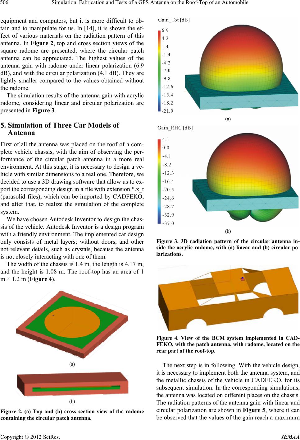 Simulation, Fabrication and Tests of a GPS Antenna on the Roof-Top of an Automobile 506 equipment and computers, but it is more difficult to ob- tain and to manipulate for us. In [14], it is shown the ef- fect of various materials on the radiation pattern of this antenna. In Figure 2, top and cross section views of the square radome are presented, where the circular patch antenna can be appreciated. The highest values of the antenna gain with radome under linear polarization (6.9 dB), and with the circular polarization (4.1 dB). They are lightly smaller compared to the values obtained without the radome. The simulation results of the antenna gain with acrylic radome, considering linear and circular polarization are presented in Figure 3. 5. Simulation of Three Car Models of Antenna First of all the antenna was placed on the roof of a com- plete vehicle chassis, with the aim of observing the per- formance of the circular patch antenna in a more real environment. At this stage, it is necessary to design a ve- hicle with similar dimensions to a real one. Therefore, we decided to use a 3D drawing software that allow us to ex- port the corresponding design in a file with extension *.x_t (parasolid files), which can be imported by CADFEKO, and after that, to realize the simulation of the complete system. We have chosen Autodesk Inventor to design the chas- sis of the vehicle. Autodesk Inventor is a design program with a friendly environment. The implemented car design only consists of metal layers; without doors, and other not relevant details, such as crystals, because the antenna is not closely interacting with one of them. The width of the chassis is 1.4 m, the length is 4.17 m, and the height is 1.08 m. The roof-top has an area of 1 m × 1.2 m (Figure 4). (a) (b) Figure 2. (a) Top and (b) cross section view of the radome containing the circular patch antenna. (a) (b) Figure 3. 3D radiation pattern of the circular antenna in- side the acrylic radome, with (a) linear and (b) circular po- larizations. Figure 4. View of the BCM system implemented in CAD- FEKO, with the patch antenna, with radome, located on the rear part of the roof-top. The next step is in following. With the vehicle design, it is necessary to implement both the antenna system, and the metallic chassis of the vehicle in CADFEKO, for its subsequent simulation. In the corresponding simulations, the antenna was located on different places on the chassis. The radiation patterns of the antenna gain with linear and circular polarization are shown in Figure 5, where it can be observed that the values of the gain reach a maximum Copyright © 2012 SciRes. JEMAA 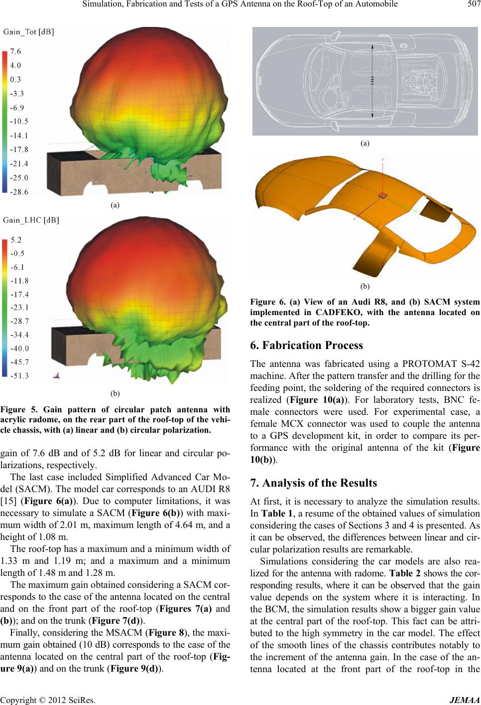 Simulation, Fabrication and Tests of a GPS Antenna on the Roof-Top of an Automobile 507 (a) (b) Figure 5. Gain pattern of circular patch antenna with acrylic radome, on the rear part of the roof-top of the vehi- cle chassis, with (a) linear and (b) circular polarization. gain of 7.6 dB and of 5.2 dB for linear and circular po- larizations, respectively. The last case included Simplified Advanced Car Mo- del (SACM). The model car corresponds to an AUDI R8 [15] (Figure 6(a)). Due to computer limitations, it was necessary to simulate a SACM (Figure 6(b)) with maxi- mum width of 2.01 m, maximum length of 4.64 m, and a height of 1.08 m. The roof-top has a maximum and a minimum width of 1.33 m and 1.19 m; and a maximum and a minimum length of 1.48 m and 1.28 m. The maximum gain obtained considering a SACM cor- responds to the case of the antenna located on the central and on the front part of the roof-top (Figures 7(a) and (b)); and on the trunk (Figure 7(d)). Finally, considering the MSACM (Figure 8), the maxi- mum gain obtained (10 dB) corresponds to the case of the antenna located on the central part of the roof-top (Fig- ure 9(a)) and on the trunk (Figure 9(d)). (a) (b) Figure 6. (a) View of an Audi R8, and (b) SACM system implemented in CADFEKO, with the antenna located on the central part of the roof-top. 6. Fabrication Process The antenna was fabricated using a PROTOMAT S-42 machine. After the pattern transfer and the drilling for the feeding point, the soldering of the required connectors is realized (Figure 10(a)). For laboratory tests, BNC fe- male connectors were used. For experimental case, a female MCX connector was used to couple the antenna to a GPS development kit, in order to compare its per- formance with the original antenna of the kit (Figure 10(b)). 7. Analysis of the Results At first, it is necessary to analyze the simulation results. In Table 1, a resume of the obtained values of simulation considering the cases of Sections 3 and 4 is presented. As it can be observed, the differences between linear and cir- cular polarization results are remarkable. Simulations considering the car models are also rea- lized for the antenna with radome. Table 2 shows the cor- responding results, where it can be observed that the gain value depends on the system where it is interacting. In the BCM, the simulation results show a bigger gain value at the central part of the roof-top. This fact can be attri- buted to the high symmetry in the car model. The effect of the smooth lines of the chassis contributes notably to the increment of the antenna gain. In the case of the an- tenna located at the front part of the roof-top in the Copyright © 2012 SciRes. JEMAA  Simulation, Fabrication and Tests of a GPS Antenna on the Roof-Top of an Automobile 508 (a) (b) (c) (d) Figure 7. Gain of the GPS antenna located on (a) the center; (b) frontal part; and (c) rear part of the roof-top, respec- tively and (d) on the trunk, using SACM. Figure 8. View of the MSACM system implemented, with the antenna located on the central part of the roof-top, in CADFEKO. Table 1. Gain of the antenna, in dB. Features Linear polarization Circular polarization Without radome 7.1 4.2 With radome 6.9 4.1 Table 2. Gain on circular polarization of the antenna with different car models . Antenna location Model Gain (dB) Central part, roof-top BCM 7.1 Front part, roof-top BCM 5.33 Rear part, roof-top BCM 5.2 On trunk BCM 7.06 Central part, roof-top SACM 10 Front part, roof-top SACM 10 Rear part, roof-top SACM 8 On trunk SACM 10 Central part, roof-top MSACM 10 Front part, roof-top MSACM 8 Rear part, roof-top MSACM 8 On trunk MSACM 10 MSACM, the decreasing of the gain value compared to the case of the SACM could be attributed to the absence of the hood. On the trunk, the values are almost as high as the case of the central part of the roof-top. The simulation results of the S21 parameter of the an- tenna with acrylic radome is shown in Figure 11, where also the experimental S21 parameter is displayed. Experimental Results Transmission-reception tests were realized using a signal Copyright © 2012 SciRes. JEMAA  Simulation, Fabrication and Tests of a GPS Antenna on the Roof-Top of an Automobile 509 (a) (b) (c) (d) Figure 9. Gain of the GPS antenna located on (a) the center, (b) frontal part, and (c) rear part of the roof-top, respec- tively and (d) on the trunk, using MSACM. (a) (b) Figure 10. Front (a) and rear view (b) of the patch circu- lantenna. Figure 11. S21 simulated and experimental parameter of the GPS antennas with acrylic radome. synthesized generator (AGILENT 83732B and 8563EC, respectively). The frequency range from 1.3 GHz up to 1.8 GHz was considered to observe the antenna behavior using a constant power generated by the transmitter. The antenna separation used was 7 cm. In Figure 12, the re- ceived power in the spectrum analyzer is shown. The oscillations could be attributed to the use of the connec- tion converters to couple the laboratory equipment, and especially by the noise given by the coaxial cable. Practical results are in following. For the test of the antenna prototype as a replacement antenna, a GPS de- velopment kit was used, which accounts with a GPS de- velopment card (ER-102-J, SiRF Star-II), and the NMEAgent data (this software shows the current loca- tion). The response of the antenna prototype with circular polarization can be analyzed in this case. Three meas- urement points were established at CIICAp parking (Fig- ure 13, Table 3). Results are also compared with a Gar- min GPS. For the test of the antenna prototype in movement, it was located on the rear roof-top of a Cavalier car model Copyright © 2012 SciRes. JEMAA  Simulation, Fabrication and Tests of a GPS Antenna on the Roof-Top of an Automobile 510 Figure 12. Power reception (S21 experimental parameter). Figure 13. Three measurement points at CIICAp parking. Table 3. Measured position at 3 points in the CIICAp par- king. With Garmin GPS Location Latitude (N) Longitude (W) Point 1 18˚58'55.6'' 99˚14'1.4'' Point 2 18˚58'54.05'' 99˚14'0.48'' Point 3 18˚58'53.85'' 99˚14'1.6'' With GPS kit (with its original antenna) Point 1 18˚58'54.52'' 99˚14'0.39'' Point 2 18˚58'54.13'' 99˚14'0.54'' Point 3 18˚58'53.95'' 99˚14'1.7'' With GPS kit (with the replacement antenna) Point 1 18˚58'55.55'' 99˚14'1.46'' Point 2 18˚58'54.21'' 99˚14'0.51'' Point 3 18˚58'53.87'' 99˚14'1.63'' 95. The trajectory is shown in Figure 14, and the meas- ured positions (marked with arrows), in Table 4. 8. Discussion Simulations of antenna performance were realized con- sidering linear and circular polarizations, but for the ex- perimental tests, the available components and equip- ment only allow us to check the response under the linear case. Transmission-reception test shows a peak of re- sponse in the range of GPS signals (1575.42 MHz). In practical tests, the replacement antenna showed sat- isfactory results (Table 3). The measurements in fixed points in comparison with the Garmin GPS are nearest using the kit with the prototype antenna. In movement, as it can be observed in Figure 14, the measured points, except for the corresponding to the CIICAp parking, are located on the university circuit, without invade build- ings, or traffic islands, that means that the measurements Figure 14. Arrows indicate the place where the measure- ments were realized. Balloons indicate the points where Google Maps display photographs on line. Table 4. Measured position of several points on the univer- sity circuit. Location Latitude (N) Longitude (W) 4 18˚58'50.52'' 99˚14'2.35'' 5 18˚58'50.25'' 99˚14'5.45'' 6 18˚58'44.05'' 99˚14'9.68'' 7 18˚58'48.64'' 99˚14'14.87'' 8 18˚58'53.03'' 99˚14'21.27'' 9 18˚58'55.65'' 99˚14'25.59'' 10 18˚58'59.95'' 99˚14'19.08'' 11 18˚58'59.16'' 99˚14'12.13'' 12 18˚58'57.51'' 99˚14'5.12'' Copyright © 2012 SciRes. JEMAA  Simulation, Fabrication and Tests of a GPS Antenna on the Roof-Top of an Automobile 511 are useful and precise. It is necessary to mention the following differences between the cars used in simulations and in practical tests: the model, the chassis material (in simulation, it is a per- fect conductor, and in the practical tests, it was covered with red painting); and the sizes are lightly different. In experimental and practical tests, the antenna performance remains as it was expected. The symmetry influences the gain value and the pat- tern shape, showing in all cases a bigger gain in the cen- tral part of the roof-top. 9. Conclusions Due to the presence of changes in the gain values of the antenna according to the system where it is immersed, it is desirable to perform the simulation considering the complete system elements, in order to know a more real behavior. However, it requires the combination of tech- nological factors in order to perform these simulations and higher computer capabilities. Surely, the antenna performance can be improved. In our BCM, our purpose was only to show a procedure of analysis based exclusively on the simulation results, en- riching the corresponding environment, implementing a complete system. In SACM and MSACM, in spite of the simplified form, it can be observed that the presence of smooth lines in- creases the gain value, compared to the BCM, due to losses reduction. The differences between SACM and MSACM, are basically in the gain corresponding to the case of the antennal located in the front part of the roof-top, due to the absence of hood in the last case, which produced a lower gain value. The modeling detail could be even further improved, but this would increase the computer memory requirements accordingly. In reception-transmission tests, the prototype shows an enough bandwidth to operate at the GPS frequency range. It was also probed that the maximum peak of response was very near to the design frequency (1.57542 GHz). The lightly variation can be attributed to the tolerance of the fabrication process. The variations in the reflection characteristics and the pattern distortion of the antenna using an acrylic radome were minimal. Additionally, it was possible to appreciate that the chassis contributes to increase the antenna gain. From the average values of the experimental tests us- ing the GPS kit in fixed points, it can be concluded that the prototype has an adequate response for its using as a replacement antenna, although the original antenna has a low noise amplifier. In practical measurements on a vehicle, the results were also satisfactory, because all measured points cor- respond to the university circuit. Some improvements could be implemented, such as, the antenna size considering alternative materials or geo- metries. The radome also can be improved using liquid acrylic or epoxy resin. The car model also can be im- proved, with the consequent increment of computer re- sources. 10. Acknowledgements Authors want to thank to EM Software & Systems (USA) Inc., for FEKO license, and to Rogers Co. for the mate- rial supplied. J. G. Vera-Dimas expresses his sincere thanks to CONACyT for the postgraduate scholarship under grant 270210/219230. REFERENCES [1] J. R. Ojha, R. Marklein and I. Widjaja, “Technological Trends of Antennas in Cars, Advances in Vehicular Net- working Technologies,” 2011. http://www.intechopen.com/books/advances-in-vehicular- network- ing-technologies/technological-trends-of-antennas-in-cars [2] P. Garg, I. Bhartia and A. Ittipiboon, “Microstrip An- tenna,” Artech House, London, 2001. [3] S. Nair, “A Multiple Antenna Global Positioning System Configuration for Enhanced Performance,” Thesis for the Degree of Master in Science, Ohio University, Athens, 2004. [4] http://tuning.deautomoviles.com.ar/articulos/accesorios/te cnologicos/navegadores-gps.html [5] http://www.aciem.org/bancoconocimiento/v/vehiculosgps /vehiculos%20gps.pdf [6] L. E. Frenzel, “Sistemas Electrónicos de Comunicación,” Alfaomega, México, 2003. [7] http://www.grupodeca.com.mx/productos-servicios/lo- calizacion-automatica-vehiculos-gps [8] http://www. Oncore.motorola.com [9] http://www.gpsenlinea.com/Vehiculos.html [10] K. Wong, “Compact and Broadband Microstrip Antennas,” Wiley Interscience, New York, 2002. doi:10.1002/0471221112 [11] A. Rasku, “Multi-Antenna Solutions for Automotive En- vironment,” M.Sc. Thesis, Tampere University of Tech- nology, Tampere, 2008. [12] M. Tecpoyotl-Torres, J. G. Vera-Dimas, R. Vargas-Bernal, M. Torres-Cisneros, A. Zamudio-Lara and V. Grimalsky, “Pentagonal Microstrip Antenna Equivalent to a Circular Microstrip Antenna for GPS Operation Frequency,” Me- morias del 7 Congreso Internacional de Cómputo en Op- timización y Software, 2009, pp. 200-208. [13] J. Hong and M. J. Lancaster, “Microstrip Filters for RF/ Microwave Applications,” Wiley Series in Microwave an Optical Engineering, New York, 2001. [14] J. G. Vera-Dimas and M. Tecpoyotl-Torres, “Kit Edu- cativo Para la Comprensión de la Propagación de Ondas Copyright © 2012 SciRes. JEMAA  Simulation, Fabrication and Tests of a GPS Antenna on the Roof-Top of an Automobile Copyright © 2012 SciRes. JEMAA 512 Electromagnéticas,” Memoria Técnica ROC & C, Vigésima Reunión de Otoño de Comunicaciones, Computación, Elec- trónica y Exposición Industrial. Acapulco, México, 2009. [15] http://www.audi.es/es/brand/es/Modelos/R8/r8_coupe/car acteristicas/Datos_tecnicos/Dimensiones.html |