

Paper Menu >>
Journal Menu >>
 Open Journal of Applied Sciences, 2012, 2, 277-282 doi:10.4236/ojapps.2012.24041 Published Online December 2012 (http://www.SciRP.org/journal/ojapps) Mechanical and Crystalline Behavior of Polymeric Nanocomposites in Presence of Natural Clay Parthajit Pal1, Mrinal Kanti Kundu1, Swinderjeetsingh Kalra2, Chapal Kumar Das1* 1Materials Science Centre, Indian Institute of Technology Kharagpur, Kharagpur, India 2Department of Chemistry, Dayanand Anglo-Vedic (D. A.-V.) College, Kanpur, India Email: *[email protected] Received October 1, 2012; revised November 2, 2012; accepted November 12, 2012 ABSTRACT Fabrication of nanocomposites from immiscible polymer blend system has been represented in this work. A new type of natural clay named Halloysite Nanotubes (HNTs) are modified by Polyethyleneimine (PEI) and these PEI grafted HNTs are incorporated into the immiscible blend system during melt mixing process to prepare halloysite based nanocompo- sites. Fourier Transform Infrared Spectroscopy (FTIR) study confirms the formation of PEI grafted HNTs. The nano- composites are characterized by SEM for morphological study and, the dispersion manners of nanoclays by Transmis- sion Electron Microscopy (TEM). Storage modulus is studied by Dynamic Mechanical Thermal Analysis (DMTA) in- strument. The tensile measurement explored better tensile property of nanocomposites as compared to the virgin blend. XRD is performed to determine the crystalline behavior of the nanocomposites as well as for blend. The above investi- gations reveal that the HNTs act as reinforcing as well as nucleating agent in the blend system. Keywords: Nanocomposite; Mechanical; Crystallinity; Halloysite; Polyethyleneimine 1. Introduction Naturally occurring tubular halloysite clay has attracted considerable interest of the researches due to its multi- purpose features. This nanomaterial may be utilized as nanofiller for polymers. Reinforcement of thermoplastic matrices with HNTs has been studied extensively by dif- ferent research groups. HNTs are used in polymeric nanocomposites to develop the mechanical strength, thermal stability, crystalline behavior etc of the polymers. Generally, layered halloysite are obtained in two poly- morphs: the hydrated form with 10 Å basal distances and the anhydrous one with 7 Å basal distances. Halloysite comprised of Al and Si at 1:1 ratio with molecular for- mula of Al2Si2O5(OH)4·nH 2O, where “n” equals to 2 and 0, corresponding hydrated and dehydrated HNTs [1,2]. Kaolin has almost similar chemical composition to HNTs but presence of interlayer water in HNTs makes it dis- tinguishable from kaolin. Weakly bonded intercalated water can be readily removed irreversibly. Halloysite has high aspect ratio (L/D ratio). Its length and diameter varies from 500 - 1000 nm and 15 - 100 nm respectively. Arti- ficially, HNTs have not been synthesized yet. At the in- ternal surface it contains gibbsite octahedral Al-OH groups, and the outer surface contains SiO4 tetrahedra. This difference results in acid-base properties for both surfaces. At pH range 2 - 8, outer surface gets negatively charged and inner lumen gets positively charged [3,4]. Grafting of HNTs can be done via covalent or non cova- lent approaches [5]. Polypropylene (PP) is widely used polymer worldwide due to its easy processibility and relatively low cost. It has good mechanical and physical properties, but its inferior properties (e.g. impact strength, low UV resistance, brittle at lower temperatures etc.) restrict its engineering applications. Many researchers have paid their attention on properties of PP/HNT com- posite [6-9]. Polyoxymethylene (POM), is also called acetal or polyacetal or polyformaldehyde etc. It consists of C-O backbone in main polymer chain [10]. This engi- neering thermoplastic have good toughness, excellent fa- tigue and creep resistance, high resistance to oxidative degradation and susceptible to UV degradation [11]. Polyethyleneimine (PEI), is a cationic hydrophilic poly- mer with amine groups [12]. Grafting of PEI had been done in case of carbon nanotubes (CNTs) [13]. It can also be used as a surface modifier for halloysites. In the present work we have chosen PP and POM be- cause both the polymers have comparable melting point leading to almost similar processing temperature [7,10]. In order to have the reasonable properties we have melt blended those polymers by melt mixing process in inter- nal melt mixer. To gain better properties, raw HNTs have been incorporated and nanocomposite prepared. Misci- *Corresponding author. Copyright © 2012 SciRes. OJAppS 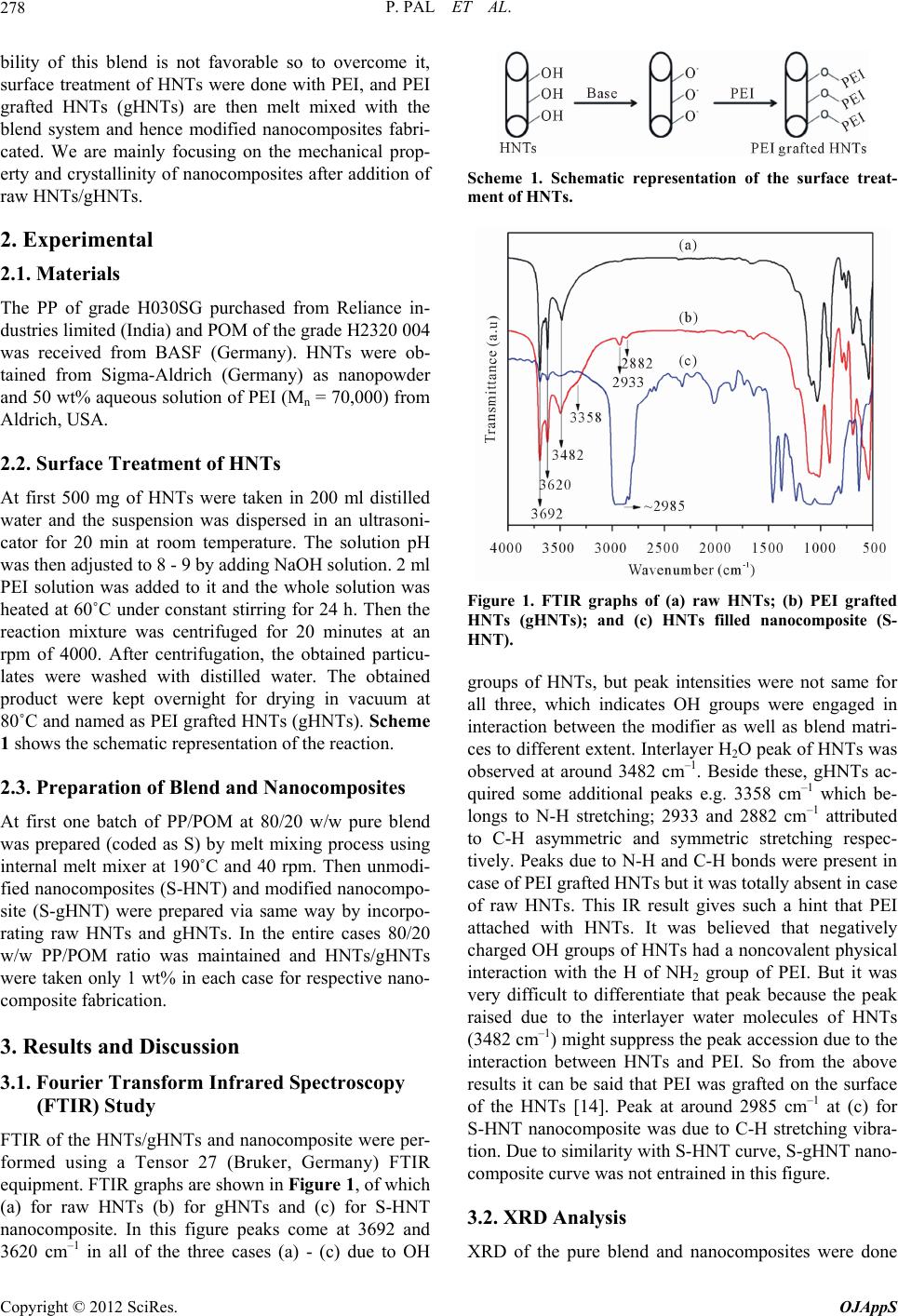 P. PAL ET AL. 278 bility of this blend is not favorable so to overcome it, surface treatment of HNTs were done with PEI, and PEI grafted HNTs (gHNTs) are then melt mixed with the blend system and hence modified nanocomposites fabri- cated. We are mainly focusing on the mechanical prop- erty and crystallinity of nanocomposites after addition of raw HNTs/gHNTs. 2. Experimental 2.1. Materials The PP of grade H030SG purchased from Reliance in- dustries limited (India) and POM of the grade H2320 004 was received from BASF (Germany). HNTs were ob- tained from Sigma-Aldrich (Germany) as nanopowder and 50 wt% aqueous solution of PEI (Mn = 70,000) from Aldrich, USA. 2.2. Surface Treatment of HNTs At first 500 mg of HNTs were taken in 200 ml distilled water and the suspension was dispersed in an ultrasoni- cator for 20 min at room temperature. The solution pH was then adjusted to 8 - 9 by adding NaOH solution. 2 ml PEI solution was added to it and the whole solution was heated at 60˚C under constant stirring for 24 h. Then the reaction mixture was centrifuged for 20 minutes at an rpm of 4000. After centrifugation, the obtained particu- lates were washed with distilled water. The obtained product were kept overnight for drying in vacuum at 80˚C and named as PEI grafted HNTs (gHNTs). Scheme 1 shows the schematic representation of the reaction. 2.3. Preparation of Blend and Nanocomposites At first one batch of PP/POM at 80/20 w/w pure blend was prepared (coded as S) by melt mixing process using internal melt mixer at 190˚C and 40 rpm. Then unmodi- fied nanocomposites (S-HNT) and modified nanocompo- site (S-gHNT) were prepared via same way by incorpo- rating raw HNTs and gHNTs. In the entire cases 80/20 w/w PP/POM ratio was maintained and HNTs/gHNTs were taken only 1 wt% in each case for respective nano- composite fabrication. 3. Results and Discussion 3.1. Fourier Transform Infrared Spectroscopy (FTIR) Study FTIR of the HNTs/gHNTs and nanocomposite were per- formed using a Tensor 27 (Bruker, Germany) FTIR equipment. FTIR graphs are shown in Figure 1, of which (a) for raw HNTs (b) for gHNTs and (c) for S-HNT nanocomposite. In this figure peaks come at 3692 and 3620 cm–1 in all of the three cases (a) - (c) due to OH Scheme 1. Schematic representation of the surface treat- ment of HNTs. Figure 1. FTIR graphs of (a) raw HNTs; (b) PEI grafted HNTs (gHNTs); and (c) HNTs filled nanocomposite (S- HNT). groups of HNTs, but peak intensities were not same for all three, which indicates OH groups were engaged in interaction between the modifier as well as blend matri- ces to different extent. Interlayer H2O peak of HNTs was observed at around 3482 cm–1. Beside these, gHNTs ac- quired some additional peaks e.g. 3358 cm–1 which be- longs to N-H stretching; 2933 and 2882 cm–1 attributed to C-H asymmetric and symmetric stretching respec- tively. Peaks due to N-H and C-H bonds were present in case of PEI grafted HNTs but it was totally absent in case of raw HNTs. This IR result gives such a hint that PEI attached with HNTs. It was believed that negatively charged OH groups of HNTs had a noncovalent physical interaction with the H of NH2 group of PEI. But it was very difficult to differentiate that peak because the peak raised due to the interlayer water molecules of HNTs (3482 cm–1) might suppress the peak accession due to the interaction between HNTs and PEI. So from the above results it can be said that PEI was grafted on the surface of the HNTs [14]. Peak at around 2985 cm–1 at (c) for S-HNT nanocomposite was due to C-H stretching vibra- tion. Due to similarity with S-HNT curve, S-gHNT nano- composite curve was not entrained in this figure. 3.2. XRD Analysis XRD of the pure blend and nanocomposites were done Copyright © 2012 SciRes. OJAppS 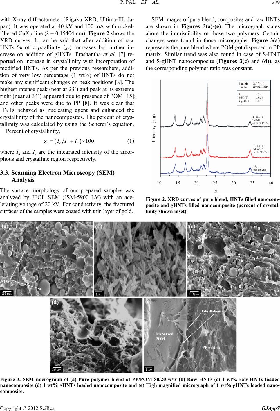 P. PAL ET AL. Copyright © 2012 SciRes. OJAppS 279 SEM images of pure blend, composites and raw HNTs are shown in Figures 3(a)-(e). The micrograph states about the immiscibility of those two polymers. Certain changes were found in those micrographs, Figure 3(a) represents the pure blend where POM got dispersed in PP matrix. Similar trend was also found in case of S-HNT and S-gHNT nanocomposite (Figures 3(c) and (d)), as the corresponding polymer ratio was constant. with X-ray diffractometer (Rigaku XRD, Ultima-III, Ja- pan). It was operated at 40 kV and 100 mA with nickel- filtered CuKα line (λ = 0.15404 nm). Figure 2 shows the XRD curves. It can be said that after addition of raw HNTs % of crystallinity (χc) increases but further in- crease on addition of gHNTs. Prashantha et al. [7] re- ported on increase in crystallinity with incorporation of modified HNTs. As per the previous researchers, addi- tion of very low percentage (1 wt%) of HNTs do not make any significant changes on peak positions [8]. The highest intense peak (near at 23˚) and peak at its extreme right (near at 34˚) appeared due to presence of POM [15]; and other peaks were due to PP [8]. It was clear that HNTs behaved as nucleating agent and enhanced the crystallinity of the nanocomposites. The percent of crys- tallinity was calculated by using the Scherer’s equation. Percent of crystallinity, 100 ccac II I (1) where Ia and Ic are the integrated intensity of the amor- phous and crystalline region respectively. 3.3. Scanning Electron Microscopy (SEM) Analysis The surface morphology of our prepared samples was analyzed by JEOL SEM (JSM-5900 LV) with an ace- lerating voltage of 20 kV. For conductivity, the fractured surfaces of the samples were coated with thin layer of gold. Figure 2. XRD curves of pure blend, HNTs filled nanocom- posite and gHNTs filled nanocomposite (percent of crystal- linity shown inset). Figure 3. SEM micrograph of (a) Pure polymer blend of PP/POM 80/20 w/w (b) Raw HNTs (c) 1 wt% raw HNTs loaded nanocomposite (d) 1 wt% gHNTs loaded nanocomposite and (e) High magnified micrograph of 1 wt% gHNTs loaded nano- omposite. c 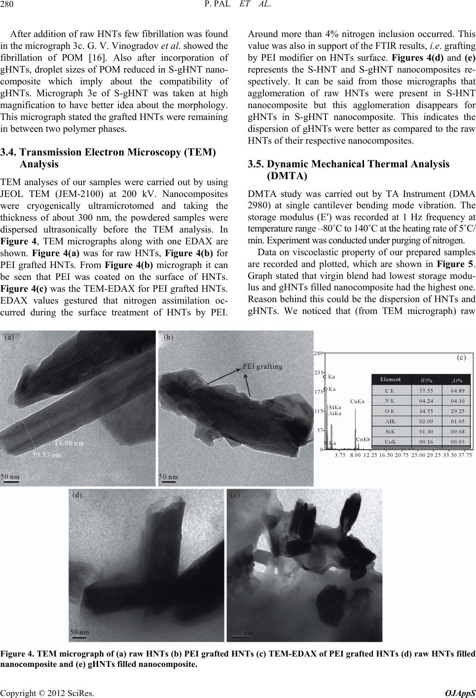 P. PAL ET AL. 280 After addition of raw HNTs few fibrillation was found in TEMf our samples were carried out by using Around more than 4% nitrogen inclusion occurred. This DMTas carried out by TA Instrument (DMA the micrograph 3c. G. V. Vinogradov et al. showed the fibrillation of POM [16]. Also after incorporation of gHNTs, droplet sizes of POM reduced in S-gHNT nano- composite which imply about the compatibility of gHNTs. Micrograph 3e of S-gHNT was taken at high magnification to have better idea about the morphology. This micrograph stated the grafted HNTs were remaining in between two polymer phases. 3.4. Transmission Electron Microscopy (TEM) Analysis analyses o JEOL TEM (JEM-2100) at 200 kV. Nanocomposites were cryogenically ultramicrotomed and taking the thickness of about 300 nm, the powdered samples were dispersed ultrasonically before the TEM analysis. In Figure 4, TEM micrographs along with one EDAX are shown. Figure 4(a) was for raw HNTs, Figure 4(b) for PEI grafted HNTs. From Figure 4(b) micrograph it can be seen that PEI was coated on the surface of HNTs. Figure 4(c) was the TEM-EDAX for PEI grafted HNTs. EDAX values gestured that nitrogen assimilation oc- curred during the surface treatment of HNTs by PEI. value was also in support of the FTIR results, i.e. grafting by PEI modifier on HNTs surface. Figures 4(d) and (e) represents the S-HNT and S-gHNT nanocomposites re- spectively. It can be said from those micrographs that agglomeration of raw HNTs were present in S-HNT nanocomposite but this agglomeration disappears for gHNTs in S-gHNT nanocomposite. This indicates the dispersion of gHNTs were better as compared to the raw HNTs of their respective nanocomposites. 3.5. Dynamic Mechanical Thermal Analysis (DMTA) A study w 2980) at single cantilever bending mode vibration. The storage modulus (E′) was recorded at 1 Hz frequency at temperature range –80˚C to 140˚C at the heating rate of 5˚C/ min. Experiment was conducted under purging of nitrogen. Data on viscoelastic property of our prepared samples are recorded and plotted, which are shown in Figure 5. Graph stated that virgin blend had lowest storage modu- lus and gHNTs filled nanocomposite had the highest one. Reason behind this could be the dispersion of HNTs and gHNTs. We noticed that (from TEM micrograph) raw Figure 4. TEM micrograph of (a) raw HNTs (b) PEI grafted HNTs (c) TEM-EDAX of PEI grafted HNTs (d) raw HNTs filled nanocomposite and (e) gHNTs filled nanocomposite. Copyright © 2012 SciRes. OJAppS 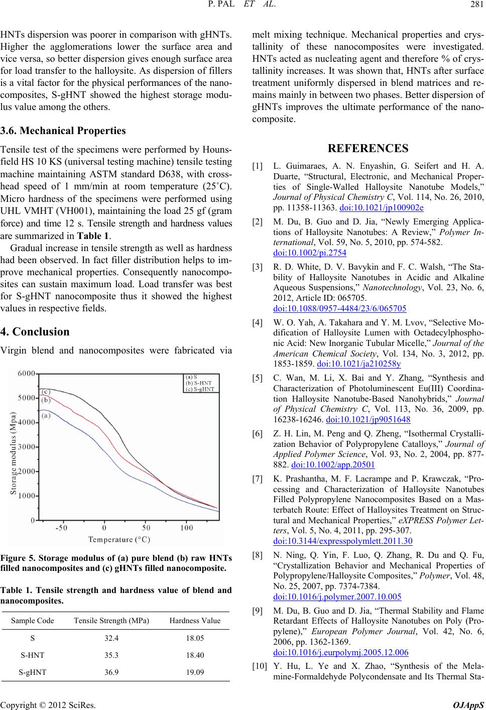 P. PAL ET AL. 281 HNTs dispersion was poorer in comparison with gHNTs. igher the agglomerations lower the surface areHa and es re performed by Houns- g machine) tensile testing ller distribution helps to im- pr nanocomposites were fabricated via vice versa, so better dispersion gives enough surface area for load transfer to the halloysite. As dispersion of fillers is a vital factor for the physical performances of the nano- composites, S-gHNT showed the highest storage modu- lus value among the others. 3.6. Mechanical Properti Tensile test of the specimens we field HS 10 KS (universal testin machine maintaining ASTM standard D638, with cross- head speed of 1 mm/min at room temperature (25˚C). Micro hardness of the specimens were performed using UHL VMHT (VH001), maintaining the load 25 gf (gram force) and time 12 s. Tensile strength and hardness values are summarized in Table 1. Gradual increase in tensile strength as well as hardness had been observed. In fact fi ove mechanical properties. Consequently nanocompo- sites can sustain maximum load. Load transfer was best for S-gHNT nanocomposite thus it showed the highest values in respective fields. 4. Conclusion Virgin blend and Figure 5. Storage modulus of (a) pure blend (b) raw HNTs filled nanocomposites and (c) gHNTs filled nanocomposite. anocomposites. Table 1. Tensile strength and hardness value of blend and n Sample Code Tensile Strength (MPa) Hardness Value S 32.4 18.05 S-T S-gHNT 36.9 19.09 HN35.3 18.40 melt mixing technique. Mechanical properties and crys- tallinity of these nanocomposites were investigated. HNT as nucleatingt and therefore crys- tallieases. It wasn that, HNTs after surface “Structural, Electronic, and Mechanical Proper- ties of Single-Walled Halloysite Nanotube Models,” Journal of Phy 114, No. 26, 2010, pp. 11358-1132e s acted agen % of nity incr show treatment uniformly dispersed in blend matrices and re- mains mainly in between two phases. Better dispersion of gHNTs improves the ultimate performance of the nano- composite. REFERENCES [1] L. Guimaraes, A. N. Enyashin, G. Seifert and H. A. Duarte, sical Chemistry C, Vol. 63. doi:10.1021/jp10090 [2] M. Du, B. Guo and D. Jia, “Newly Emerging Applica- tions of Halloysite Nanotubes: A Review,” Polymer In- ternational, Vol. 59, No. 5, 2010, pp. 574-582. doi:10.1002/pi.2754 [3] R. D. White, D. V. Bavykin and F. C. Walsh, “The Sta- 4/23/6/065705 bility of Halloysite Nanotubes in Acidic and Alkaline Aqueous Suspensions,” Nanotechnology, Vol. 23, No. 6, 2012, Article ID: 065705. doi:10.1088/0957-448 , Vol. 134, No. 3, 2012, pp. [4] W. O. Yah, A. Takahara and Y. M. Lvov, “Selective Mo- dification of Halloysite Lumen with Octadecylphospho- nic Acid: New Inorganic Tubular Micelle,” Journal of the American Chemical Society 1853-1859. doi:10.1021/ja210258y [5] C. Wan, M. Li, X. Bai and Y. Zhang, “Synthesis and Characterization of Photoluminescent Eu(III) Coordina- tion Halloysite Nanotube-Based Nanohybrids,” Journal of Physical Chemistry C, Vol. 113, No. 36, 2009, pp. 16238-16246. doi:10.1021/jp9051648 [6] Z. H. Lin, M. Peng and Q. Zheng, “Isothermal Crystalli- zation Behavior of Polypropylene Catalloys,” Journal of Applied Polymer Science, Vol. 93, No. 2, 2004, pp. 877- 882. doi:10.1002/app.20501 [7] K. Prashantha, M. F. Lacrampe and P. Krawczak, “Pro- ies,” eXPRESS Polymer Let- cessing and Characterization of Halloysite Nanotubes Filled Polypropylene Nanocomposites Based on a Mas- terbatch Route: Effect of Halloysites Treatment on Struc- tural and Mechanical Propert ters, Vol. 5, No. 4, 2011, pp. 295-307. doi:10.3144/expresspolymlett.2011.30 [8] N. Ning, Q. Yin, F. Luo, Q. Zhang, R. Du and Q. Fu, “Crystallization Behavior and Mechanical Properties of Polypropylene/Halloysite Composites,” Polymer, Vol. 48, No. 25, 2007, pp. 7374-7384. doi:10.1016/j.polymer.2007.10.005 [9] M. Du, B. Guo and D. Jia, “Thermal Stability and Flame Retardant Effects of Halloysite Nanotubes on Poly (Pro- pylene),” European Polymer Journal, Vol. 42, No. 6, 2006, pp. 1362-1369. doi:10.1016/j.eurpolymj.2005.12.006 mine-Formaldehyde Polycondensate and Its Thermal Sta- [10] Y. Hu, L. Ye and X. Zhao, “Synthesis of the Mela- Copyright © 2012 SciRes. OJAppS  P. PAL ET AL. 282 bilization Effect on Polyoxymethylene,” Polymer, Vol. 47, No. 8, 2006, pp. 2649-2659. doi:10.1016/j.polymer.2006.02.050 ChemTec Publish- r the Dehydration of mparison with Glu- logy, Vol. 48, No. 3, 2006, pp. 244- [11] G. Wypych, “Handbook of Polymers,” ing, Toronto, 2012. [12] P. S. Rao, B. Smitha, S. Sridhar and A. Krishnaiah, “Pre- paration and Performance of Poly(vinyl Alcohol)/Poly- ethyleneimine Blend Membranes fo 1,4-Dioxane by Pervaporation: Co taraldehyde Cross-Linked Membranes,” Separation and Purification Techno 254. doi:10.1016/j.seppur.2005.07.031 [13] E. J. Petersen, R. A. Pinto, D. J. Mai, P. F. Landrum and W. J. Weber Jr., “Influence of Polyethyleneimine Graft- ings of Multi-Walled Carbon Nanotubes on Their Accu- mulation and Elimination by and Toxicity to Daphnia magna,” Environmental Science & Technology, Vol. 45, No. 3, 2011, pp. 1133-1138. doi:10.1021/es1030239 [14] B. Gao, P. Jiang and H. Lei, “Studies on Adsorption Property of Novel Composite Adsorption Material PEI/ SiO for Uric Acid,” Materials Letters, Vol. 60, No 2 200 . 28, 6, pp. 3398-3404. doi:10.1016/j.matlet.2006.03.086 [15] J. Wang, K. H. Hu, Y. F. Xu and X. G. Hu, “Structural, Thermal, and Tribological Properties of Intercalated Poly- oxymethylene/Molybdenum Disulfide Nanocomposites,” Journal of Applied Polymer Science, Vol. 110, No. 1, 2008, pp. 91-96. doi:10.1002/app.28519 [16] G. V. Vinogradov and B. V. Yarlykov, “Fibrillation in the Flow of Polyoxymethylene Melts,” Polymer, Vol. 16, No. 8, 1975, pp. 609-614. doi:10.1016/0032-3861(75)90156-1 Copyright © 2012 SciRes. OJAppS |