

Paper Menu >>
Journal Menu >>
 Journal of Geographic Information System, 2012, 4, 444-461 http://dx.doi.org/10.4236/jgis.2012.45049 Published Online October 2012 (http://www.SciRP.org/journal/jgis) Land Capability Index Mapping for Waste Disposal Landuse Option Using Geographic Information System (GIS) in Enugu Area, South Eastern Nigeria Augustine Onunkwo-Akunne, Samuel Okechukwu Onyekuru, Godwin Ifedilichukwu Nwankwor Department of Geology, Federal University of Technology Owerri, Owerri, Nigeria Email: [email protected] Received January 2, 2012; revised February 5, 2012; accepted March 14, 2012 ABSTRACT The projected 300% growth rate in the population of Enugu area and its environs by the year 2020 and the expected increase in waste generation necessitated the need to map out areas for waste disposal for future utilization and as a protective strategy for the environment in Enugu area. Land capability index mapping using Geographic Information System (GIS) is one of the appropriate tools required for solving this problem. A total of 12 landuse determinants were selected as thematic data layers, and as basic factors influencing the choice of waste disposal landuse option in the area. The themes (thematic maps) generated from field/laboratory measurements and from literature, include slope, water table, surface and subsurface water conditions, elevation, geology, soil, drainage and geo-structural stability (fault, ero- sion, landslide and flooding) maps. The maps were scanned, digitized, georeferenced, and polygonized using autocard drawing capabilities to convert them into vector format and later exported to arc view software for analysis. The final processing using overlay model builder yields layers that display areas of preferred waste disposal sites in a map form, which generally shows areas of varying suitability (suitable, moderately (low) suitable and unsuitable). The waste dis- posal map of Enugu area shows that blocks 1 (Obeagu area) and 3 (Ebe/Nsude areas) represent suitable and unsuitable areas, respectively, while block 2 (Ngwo area) has low suitability for waste disposal. Keywords: Landuse; Thematic Maps; Waste Disposal; Land Capability 1. Introduction The purpose of landuse planning is to make the best, most sensible, practical, safe and efficient use of each parcel of land [1]. Mapping of a land unit for a particular purpose is an aspect of Landuse planning which ensures maximum and safe utilization of land. Enugu area under investigation is presently witnessing high rate of popula- tion growth. Accordingly, a projection of the population of Enugu area is pegged at approximately 300%, giving rise to a population figure of about 3,237,298 people by the year 2020, [2]. Problems of improper waste disposal are always associated with over population in developing countries of the world. This condition usually causes en- vironmental degradation leading to contamination/pollu- tion of the environment. It is therefore, necessary to map out areas of varying capabilities for waste attenuation and containment in the Enugu area for future utilization and as a protective strategy for the environment. Site evaluation for waste disposal involves the under- standing of basic soil components and properties, mecha- nisms operating in the soil and limitations of the mecha- nisms in terms of pollutant loading rates. It also describes the important criteria used in evaluating land for waste disposal. The factors to be considered in such evaluations include: climate, topography, drainage, soil properties, groundwater, slope, surface water, fault and flood poten- tial [3-11]. The application of Geographic Information System (GIS) in the evaluation of land has widely been ac- claimed to facilitate efficient decision making and plan- ning of land use options, [12]. GIS consists of a set of computerized tools and procedures that can be used to effectively store, retrieve, overlay, correlate, manipulate, analyze, query, display (both graphically and numerically) and disseminate land related information, [13]. This approach is applied in the determination of areas with varying degrees of suitability for waste disposal land use option in the Enugu area and environs. 1.1. Location of Study Area The study area is located within Latitudes 6˚16'N and 6˚31'N and Longitudes 7˚20'E and 7˚41'E covering an C opyright © 2012 SciRes. JGIS 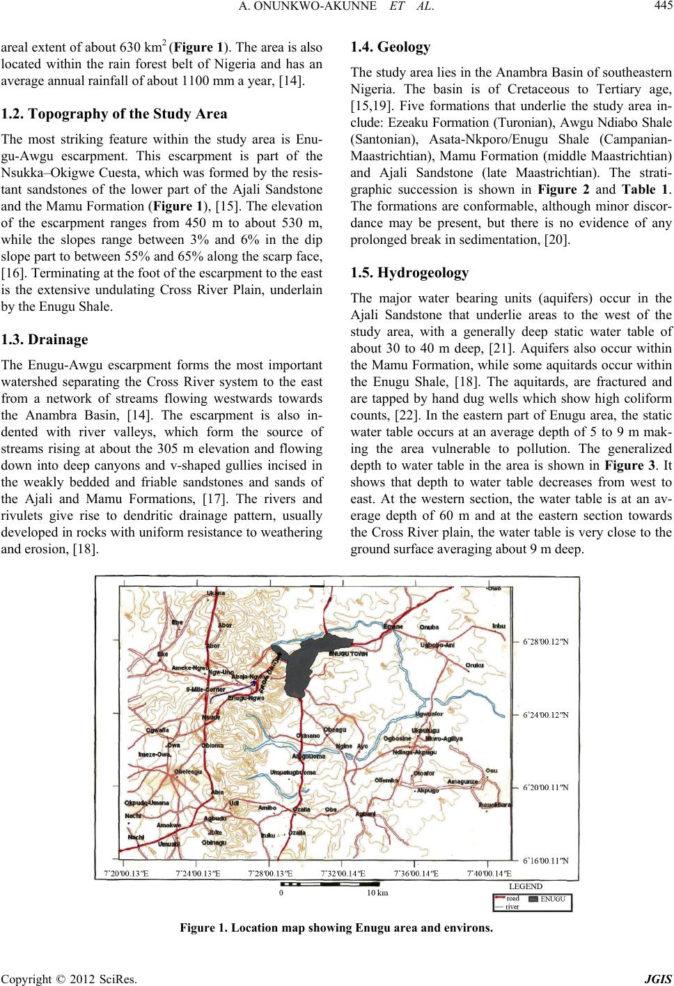 A. ONUNKWO-AKUNNE ET AL. 445 areal extent of about 630 km2 (Figure 1). The area is also located within the rain forest belt of Nigeria and has an average annual rainfall of about 1100 mm a year, [14]. 1.2. Topography of the Study Area The most striking feature within the study area is Enu- gu-Awgu escarpment. This escarpment is part of the Nsukka–Okigwe Cuesta, which was formed by the resis- tant sandstones of the lower part of the Ajali Sandstone and the Mamu Formation (Figure 1), [15]. The elevation of the escarpment ranges from 450 m to about 530 m, while the slopes range between 3% and 6% in the dip slope part to between 55% and 65% along the scarp face, [16]. Terminating at the foot of the escarpment to the east is the extensive undulating Cross River Plain, underlain by the Enugu Shale. 1.3. Drainage The Enugu-Awgu escarpment forms the most important watershed separating the Cross River system to the east from a network of streams flowing westwards towards the Anambra Basin, [14]. The escarpment is also in- dented with river valleys, which form the source of streams rising at about the 305 m elevation and flowing down into deep canyons and v-shaped gullies incised in the weakly bedded and friable sandstones and sands of the Ajali and Mamu Formations, [17]. The rivers and rivulets give rise to dendritic drainage pattern, usually developed in rocks with uniform resistance to weathering and erosion, [18]. 1.4. Geology The study area lies in the Anambra Basin of southeastern Nigeria. The basin is of Cretaceous to Tertiary age, [15,19]. Five formations that underlie the study area in- clude: Ezeaku Formation (Turonian), Awgu Ndiabo Shale (Santonian), Asata-Nkporo/Enugu Shale (Campanian- Maastrichtian), Mamu Formation (middle Maastrichtian) and Ajali Sandstone (late Maastrichtian). The strati- graphic succession is shown in Figure 2 and Table 1. The formations are conformable, although minor discor- dance may be present, but there is no evidence of any prolonged break in sedimentation, [20]. 1.5. Hydrogeology The major water bearing units (aquifers) occur in the Ajali Sandstone that underlie areas to the west of the study area, with a generally deep static water table of about 30 to 40 m deep, [21]. Aquifers also occur within the Mamu Formation, while some aquitards occur within the Enugu Shale, [18]. The aquitards, are fractured and are tapped by hand dug wells which show high coliform counts, [22]. In the eastern part of Enugu area, the static water table occurs at an average depth of 5 to 9 m mak- ing the area vulnerable to pollution. The generalized depth to water table in the area is shown in Figure 3. It shows that depth to water table decreases from west to east. At the western section, the water table is at an av- erage depth of 60 m and at the eastern section towards the Cross River plain, the water table is very close to the ground surface averaging about 9 m deep. Figure 1. Location map showing Enugu area and environs. Copyright © 2012 SciRes. JGIS 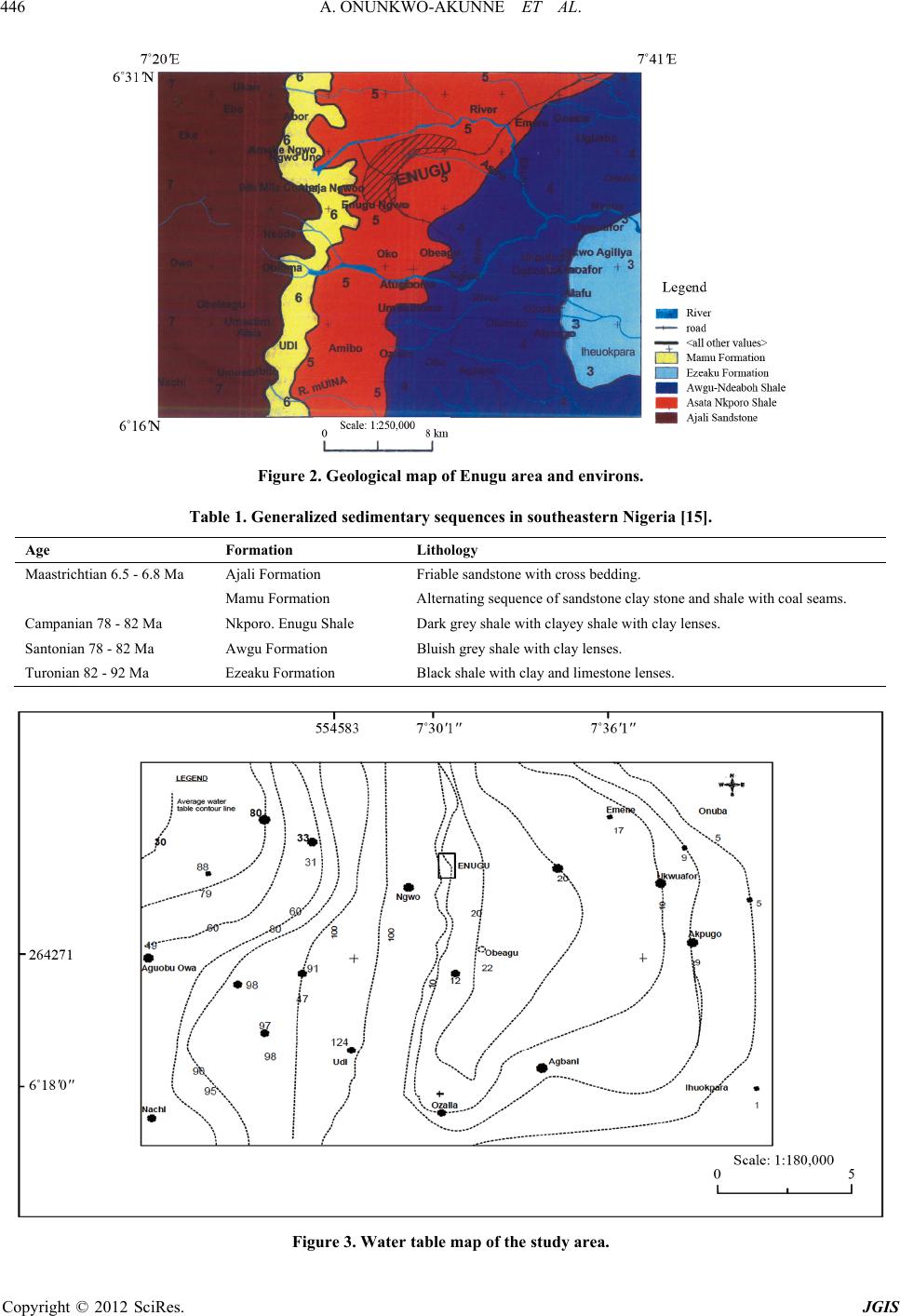 A. ONUNKWO-AKUNNE ET AL. 446 Figure 2. Geological map of Enugu area and environs. Table 1. Generalized sedimentary sequences in southeastern Nigeria [15]. Age Formation Lithology Maastrichtian 6.5 - 6.8 Ma Ajali Formation Friable sandstone with cross bedding. Mamu Formation Alternating sequence of sandstone clay stone and shale with coal seams. Campanian 78 - 82 Ma Nkporo. Enugu Shale Dark grey shale with clayey shale with clay lenses. Santonian 78 - 82 Ma Awgu Formation Bluish grey shale with clay lenses. Turonian 82 - 92 Ma Ezeaku Formation Black shale with clay and limestone lenses. Figure 3. Water table map of the study area. Copyright © 2012 SciRes. JGIS 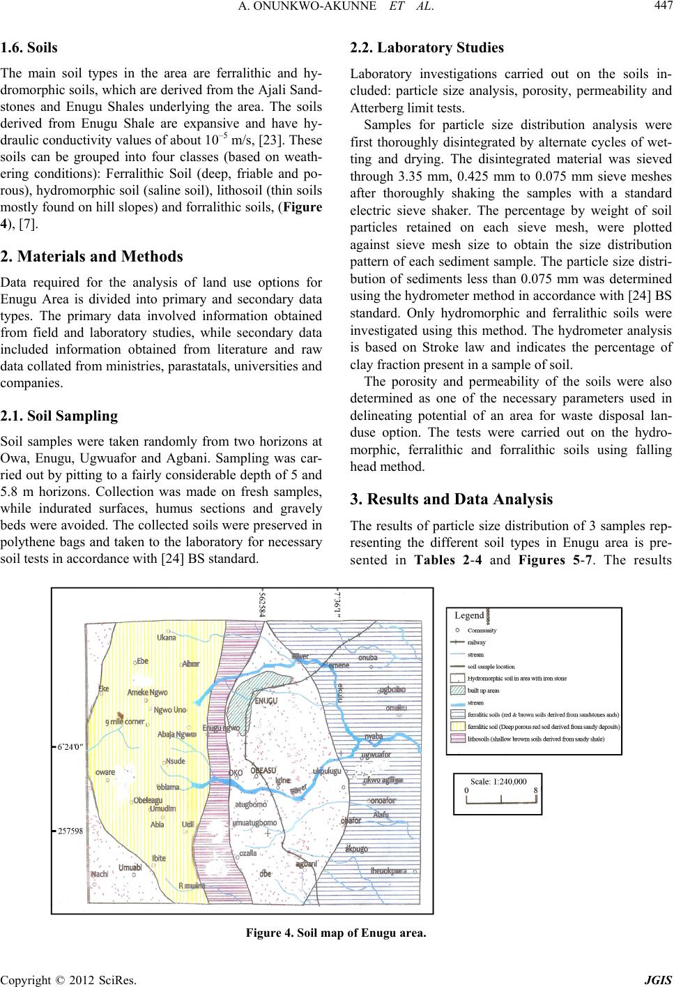 A. ONUNKWO-AKUNNE ET AL. Copyright © 2012 SciRes. JGIS 447 1.6. Soils 2.2. Laboratory Studies The main soil types in the area are ferralithic and hy- dromorphic soils, which are derived from the Ajali Sand- stones and Enugu Shales underlying the area. The soils derived from Enugu Shale are expansive and have hy- draulic conductivity values of about 10–5 m/s, [23]. These soils can be grouped into four classes (based on weath- ering conditions): Ferralithic Soil (deep, friable and po- rous), hydromorphic soil (saline soil), lithosoil (thin soils mostly found on hill slopes) and forralithic soils, (Figure 4), [7]. Laboratory investigations carried out on the soils in- cluded: particle size analysis, porosity, permeability and Atterberg limit tests. Samples for particle size distribution analysis were first thoroughly disintegrated by alternate cycles of wet- ting and drying. The disintegrated material was sieved through 3.35 mm, 0.425 mm to 0.075 mm sieve meshes after thoroughly shaking the samples with a standard electric sieve shaker. The percentage by weight of soil particles retained on each sieve mesh, were plotted against sieve mesh size to obtain the size distribution pattern of each sediment sample. The particle size distri- bution of sediments less than 0.075 mm was determined using the hydrometer method in accordance with [24] BS standard. Only hydromorphic and ferralithic soils were investigated using this method. The hydrometer analysis is based on Stroke law and indicates the percentage of clay fraction present in a sample of soil. 2. Materials and Methods Data required for the analysis of land use options for Enugu Area is divided into primary and secondary data types. The primary data involved information obtained from field and laboratory studies, while secondary data included information obtained from literature and raw data collated from ministries, parastatals, universities and companies. The porosity and permeability of the soils were also determined as one of the necessary parameters used in delineating potential of an area for waste disposal lan- duse option. The tests were carried out on the hydro- morphic, ferralithic and forralithic soils using falling head method. 2.1. Soil Sampling Soil samples were taken randomly from two horizons at Owa, Enugu, Ugwuafor and Agbani. Sampling was car- ried out by pitting to a fairly considerable depth of 5 and 5.8 m horizons. Collection was made on fresh samples, while indurated surfaces, humus sections and gravely beds were avoided. The collected soils were preserved in polythene bags and taken to the laboratory for necessary soil tests in accordance with [24] BS standard. 3. Results and Data Analysis The results of particle size distribution of 3 samples rep- resenting the different soil types in Enugu area is pre- ented in Tables 2-4 and Figures 5-7. The results s Figure 4. Soil map of Enugu area.  A. ONUNKWO-AKUNNE ET AL. 448 Table 2. Grain size data for ferralithic soil. Sieve Size (mm) Mass retained Cumulative mass retained (g) % Cum-mass retained % Passing 5.56 0 0 0 100 3.35 0.2 0.2 0.04 99.96 2.0 2.1 2.3 0.46 99.54 1.18 33.1 35.4 7.08 92.92 0.6 60.8 96.2 19.24 80.76 0.425 98.6 194.8 38.96 61.04 0.5 97.8 292.6 58.52 41.48 0.212 84.0 377.6 75.52 14.48 0.15 85.6 463.2 92.64 7.36 0.075 32.8 496.0 99.20 0.8 Received 3.4 499.4 99.98 0.02 Table 3. Grain size data for forralithic soil. Sieve Size (mm) Mass retained Cumulative mass retained % Cum-mass retained % Passing 3.35 0 0 0 100 2.0 0.2 0.2 0.04 99.56 1.18 2.8 3.0 0.6 99.4 0.6 8.7 11.7 2.34 97.66 0.425 19.1 30.8 6.16 93.84 0.3 21.7 52.5 10.5 89.5 0.212 56.0 108.5 21.7 78.3 0.15 153.2 261.7 52.34 47.3 0.075 191.0 452.7 90.54 9.46 Received 47.0 495.7 99.94 0.06 Table 4. Grain size data for hydromorphic soil. Sieve Size (mm) Mass retained(g) Cumulative mass retained (g) % Cum-mass retained % Passing 28.0 0 10 0 100 19.0 18.4 18.4 374 96.26 14.0 6.2 24.6 5.00 95.00 10.0 27.3 51.9 10.55 89.45 5.6 76.6 131.5 26.75 73.25 3.35 81.3 212.8 43.26 56.12 2.0 70.6 283.4 57.65 42.35 1.18 57.3 340.9 67.34 30.66 0.6 30.5 371.4 75.34 24.46 0.425 13.4 384.8 78.28 21.72 0.3 10.5 395.6 80.41 19.59 0.212 6.3 401.6 81.69 18.31 0.15 26.3 427.9 87.04 12.96 0.075 36.3 464.2 94.43 5.57 Received 17.7 481.9 98.03 1.97 Copyright © 2012 SciRes. JGIS  A. ONUNKWO-AKUNNE ET AL. 449 Figure 5. Grain size distribution of the forralithic soil (Owa). Figure 6. Grain size distribution of the ferralithic soil (Ugwuafor). Figure 7. Grain size distribution of the hydromorphic soil (Enugu). Copyright © 2012 SciRes. JGIS  A. ONUNKWO-AKUNNE ET AL. Copyright © 2012 SciRes. JGIS 450 show that forralithic soils can be grouped as sandy clay soils while hydromorphic and ferralithic soils are silty clay soils. The plots of hydrometer analysis for the two soil types (ferralithic and hydromorphic soils) are shown in Fig- ures 8(a) and (b), which show that the clay fraction of the hydromorphic soil is 13% and that of ferralithic soil is 13.5% in the analyzed samples. The result of the falling head test for some of soil types in the study area is shown in Table 5. The For- ralithic and hydromorphic soils have higher porosity and permeability which corroborates the work of [25]. (a) (b) Figure 8. (a) Plot of grain size analysis result using hydrometer for ferralithic soil; (b) Plot of grain size analysis result using hydrometer for hydromorphic soil.  A. ONUNKWO-AKUNNE ET AL. 451 Table 5. Permeability and porosity of soils in Enugu area. Soil Type Pe rm eabi lity (cm/s) Porosity (%) Hydromorphic Soil 1.97 × 10⁻² 31 Ferralithic Soil 1.89 × 10⁻² 30 Forralithic Soil 1.92 × 10⁻² 31 Similarly, the following physical properties of litho- soils that also underlie part of the study area have also been defined, [16]: shear strength = 88.36 N/m2, porosity = 30% and permeability is 1.70 cm/s, soil group is silty sand. 3.1. Engineering Classification of Soils The Unified Soil Classification System (USCS; Table 6) used particle size distribution and Atterberg Limit Data (Tables 7-9) to describe two main soil groups in the study area: coarse and fine grained soils. The plasticity chart (Figure 9) also used grain size distribution and Atterberg limit data (Tables 7-9) to characterize three classes of soils in the study area (Forralithic Soil, Hy- dromorphic Soil and Ferralithic Soil): Forralithic soils, plotted on CL-ML field (Figure 9) representing silty clay and poorly graded soils. Hydromorphic soil plotted on SP-CL field which is silty clay and poorly sorted soils. Ferralithic soil plotted on SW-CL field which is silty clay and well sorted soils. 3.2. Thematic Maps Twelve thematic maps generated from the various field and laboratory operations and from literature were em- ployed as basic landuse determinants in the study area. The maps are the themes that form data layers for Geo- graphic Information System (GIS) operation. The the- matic maps were first scanned at 150 dpi (dot per inch) esolutions, digitized, polygonized and georeferenced r Table 6. Unified soil classification system. Major Divisions Subdivisions USCS Symbol Typical Names Laboratory Classification Criteria Remarks GW Well Graded Gravels, or gravel- sand mixtures with little or no fines Less than 5% fines C ≥ –4 and 1 ≤ C ≤ 3 GP Poorly Graded Gravels, or gravely sands, little or no fines Less than 5% fines Does not meet C and or C criteria listed above GM Silty Gravels and sand mixtures More than 12% fines Minus No. 40 Soils plot above A Line Gravels (More than 50% Retained on No. 4 Sieve GC Silty Gravels, Gravels and clay Mixtures More than 12% fines Minus No. 40 Soils plot above A Line SW Well graded Sands or Gravelly Sands, little or no fines Less than 5% fines C ≥ –6 and 1 ≤ C ≤ 3 SP Poorly Graded Sands or Gravelly Sands little or no fines Less than 5% fines Does not meet C and or C criteria listed above SM Silty Sands, Sand Silt Mixtures More than 12% fines Minus No. 40 Soils plot above A Line Coarse Grained Soil (More than 50% Retained on No. 200 Sieve Sands (50% or more of coarse fraction passing No. 4 Sieve) SC Clayey Sands, Clay-Sand Mixtures More than 12% fines Minus No. 40 Soils plot above A Line ML Inorganic silts, rock, flour, silts of low plasticity Inorganic soil PL < 4 or Plots below A Line CL Inorganic Clays of low plasticity (Gravel Clays, Sandy Clays, etc. Inorganic soil PL > 7 or Plots above A Line Silts and Clays (Liquid Limit < 50%) OL Organic Silts, Organic Clays of low plasticity Organic soil LL (Oven-Dried) LL (Not Oven Dried) 0.75 MH Inorganic silts, micaceous silts, silts of high plasticity Inorganic soil Plots below A Line CH Inorganic highly plastic Clays, fat clays, silty clays, etc. Inorganic soil Plots on or above A line Fine Grained Soils (50% or more passes No. 200 Sieve Silts and Clays (Liquid Limit 50% or more) OH Organic Silts and Organic Clays of high plasticity Organic soil LL (Oven-Dried) LL (Not Oven Dried) 0.75 Peat Highly Organic PT Peat and other highly organic soils Primary organic matter, dark in colour Copyright © 2012 SciRes. JGIS 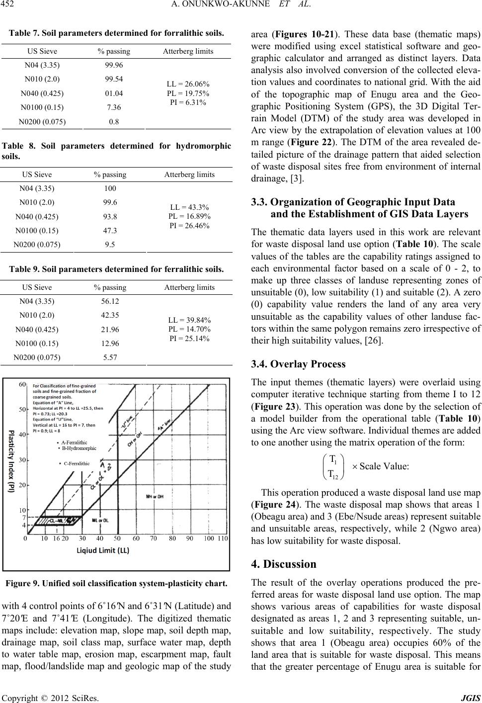 A. ONUNKWO-AKUNNE ET AL. 452 Table 7. Soil parameters determined for forralithic soils. US Sieve % passing Atterberg limits N04 (3.35) 99.96 N010 (2.0) 99.54 N040 (0.425) 01.04 N0100 (0.15) 7.36 N0200 (0.075) 0.8 LL = 26.06% PL = 19.75% PI = 6.31% Table 8. Soil parameters determined for hydromorphic soils. US Sieve % passing Atterberg limits N04 (3.35) 100 N010 (2.0) 99.6 N040 (0.425) 93.8 N0100 (0.15) 47.3 N0200 (0.075) 9.5 LL = 43.3% PL = 16.89% PI = 26.46% Table 9. Soil parameters determined for ferralithic soils. US Sieve % passing Atterberg limits N04 (3.35) 56.12 N010 (2.0) 42.35 N040 (0.425) 21.96 N0100 (0.15) 12.96 N0200 (0.075) 5.57 LL = 39.84% PL = 14.70% PI = 25.14% Figure 9. Unified soil classification system-plasticity chart. with 4 control points of 6˚16'N and 6˚31'N (Latitude) and 7˚20'E and 7˚41'E (Longitude). The digitized thematic maps include: elevation map, slope map, soil depth map, drainage map, soil class map, surface water map, depth to water table map, erosion map, escarpment map, fault map, flood/landslide map and geologic map of the study area (Figures 10-21). These data base (thematic maps) were modified using excel statistical software and geo- graphic calculator and arranged as distinct layers. Data analysis also involved conversion of the collected eleva- tion values and coordinates to national grid. With the aid of the topographic map of Enugu area and the Geo- graphic Positioning System (GPS), the 3D Digital Ter- rain Model (DTM) of the study area was developed in Arc view by the extrapolation of elevation values at 100 m range (Figure 22). The DTM of the area revealed de- tailed picture of the drainage pattern that aided selection of waste disposal sites free from environment of internal drainage, [3]. 3.3. Organization of Geographic Input Data and the Establishment of GIS Data Layers The thematic data layers used in this work are relevant for waste disposal land use option (Table 10). The scale values of the tables are the capability ratings assigned to each environmental factor based on a scale of 0 - 2, to make up three classes of landuse representing zones of unsuitable (0), low suitability (1) and suitable (2). A zero (0) capability value renders the land of any area very unsuitable as the capability values of other landuse fac- tors within the same polygon remains zero irrespective of their high suitability values, [26]. 3.4. Overlay Process The input themes (thematic layers) were overlaid using computer iterative technique starting from theme I to 12 (Figure 23). This operation was done by the selection of a model builder from the operational table (Table 10) using the Arc view software. Individual themes are added to one another using the matrix operation of the form: 1 12 T Scale Value: T This operation produced a waste disposal land use map (Figure 24). The waste disposal map shows that areas 1 (Obeagu area) and 3 (Ebe/Nsude areas) represent suitable and unsuitable areas, respectively, while 2 (Ngwo area) has low suitability for waste disposal. 4. Discussion The result of the overlay operations produced the pre- ferred areas for waste disposal land use option. The map shows various areas of capabilities for waste disposal designated as areas 1, 2 and 3 representing suitable, un- suitable and low suitability, respectively. The study shows that area 1 (Obeagu area) occupies 60% of the land area that is suitable for waste disposal. This means that the greater percentage of Enugu area is suitable for Copyright © 2012 SciRes. JGIS 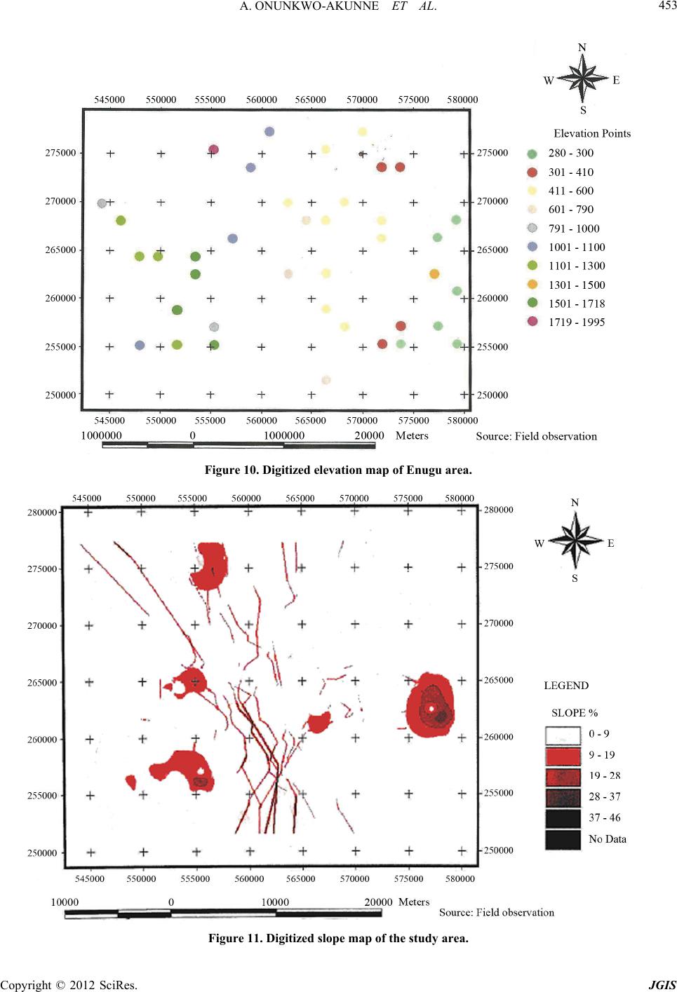 A. ONUNKWO-AKUNNE ET AL. 453 Figure 10. Digitized elevation map of Enugu area. Figure 11. Digitized slope map of the study area. Copyright © 2012 SciRes. JGIS 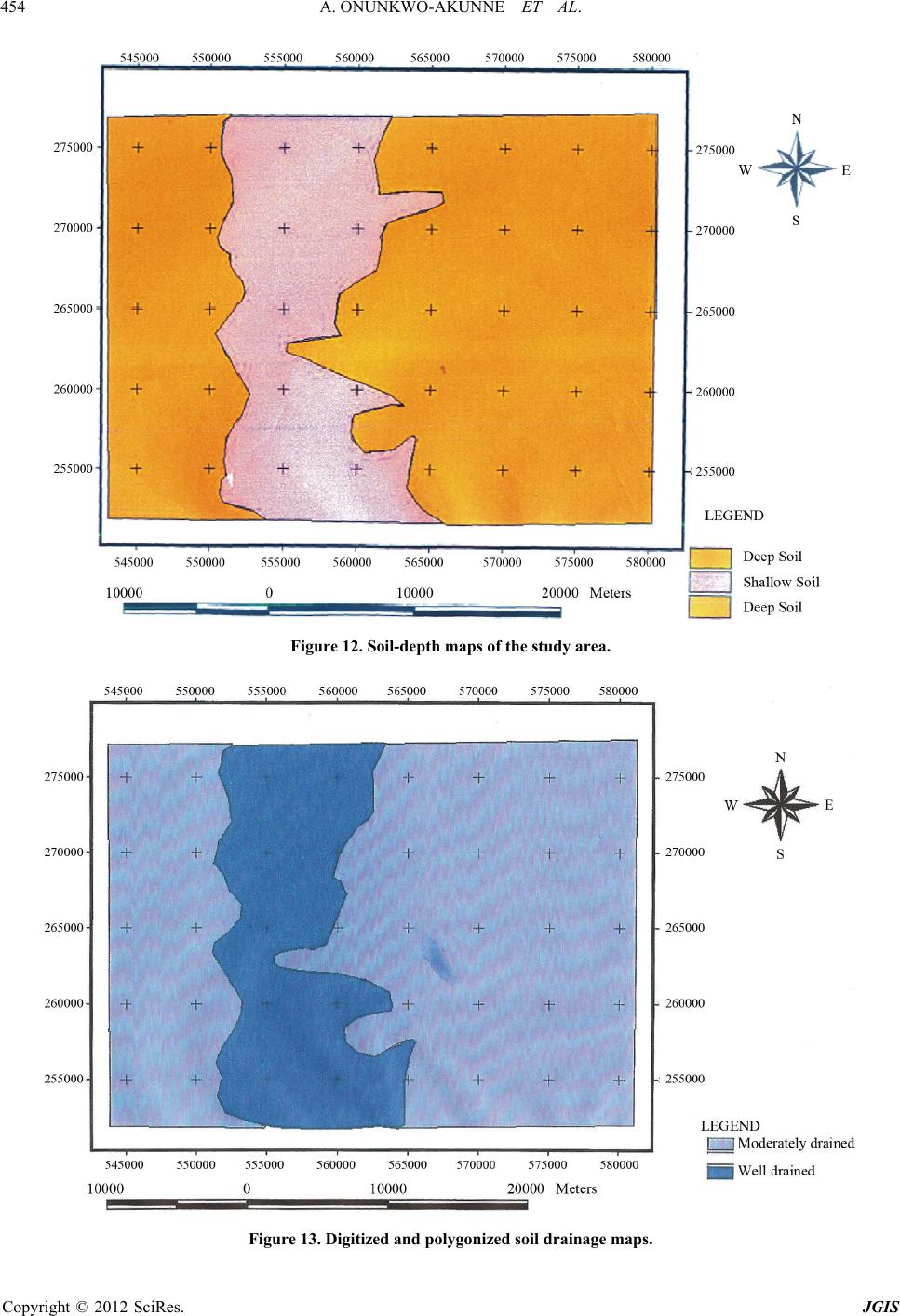 A. ONUNKWO-AKUNNE ET AL. 454 Figure 12. Soil-depth maps of the study are a . Figure 13. Digitized and polygonized soil drainage maps. Copyright © 2012 SciRes. JGIS 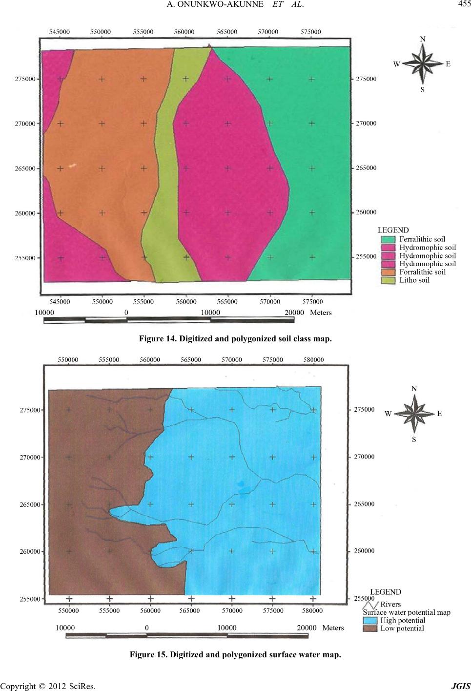 A. ONUNKWO-AKUNNE ET AL. 455 Figure 14. Digitized and polygonized soil class map. Figure 15. Digitized and polygonized surface water map. Copyright © 2012 SciRes. JGIS 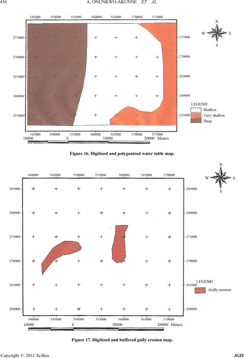 A. ONUNKWO-AKUNNE ET AL. 456 Figure 16. Digitized and polygonized wate r table map. Figure 17. Digitized and buffered gully erosion map. Copyright © 2012 SciRes. JGIS 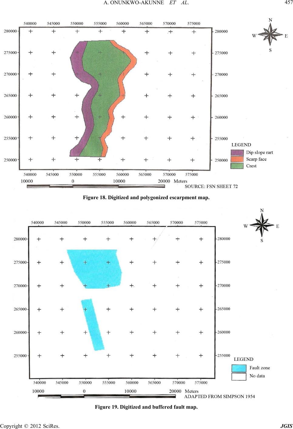 A. ONUNKWO-AKUNNE ET AL. 457 Figure 18. Digitized and polygonized esc ar pment map. Figure 19. Digitized and buffered fault map. Copyright © 2012 SciRes. JGIS 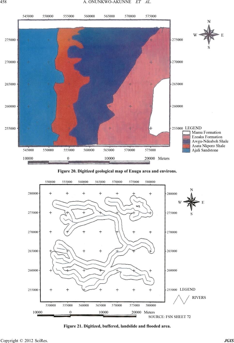 A. ONUNKWO-AKUNNE ET AL. 458 Figure 20. Digitized geological map of Enugu area and environs. Figure 21. Digitized, buffered, landslide and flooded area. Copyright © 2012 SciRes. JGIS 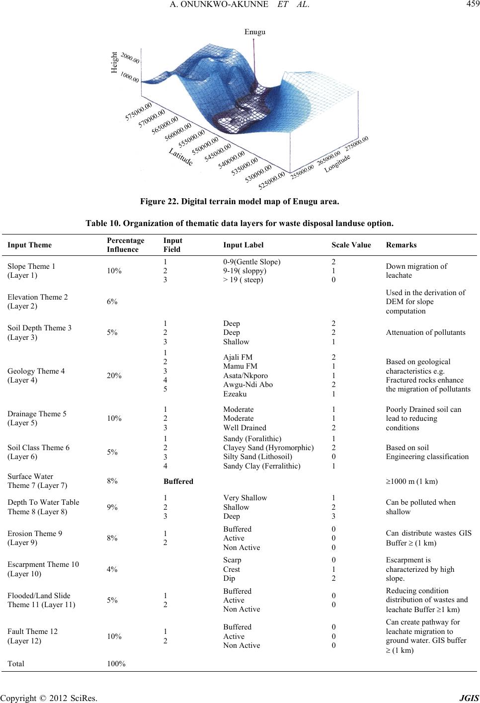 A. ONUNKWO-AKUNNE ET AL. 459 Figure 22. Digital terrain model map of Enugu area. Table 10. Organization of thematic data layers for w aste disposal landuse option. Input Theme Percentage Influence Input Field Input Label Scale Value Remarks Slope Theme 1 (Layer 1) 10% 1 2 3 0-9(Gentle Slope) 9-19( sloppy) > 19 ( steep) 2 1 0 Down migration of leachate Elevation Theme 2 (Layer 2) 6% Used in the derivation of DEM for slope computation Soil Depth Theme 3 (Layer 3) 5% 1 2 3 Deep Deep Shallow 2 2 1 Attenuation of pollutants Geology Theme 4 (Layer 4) 20% 1 2 3 4 5 Ajali FM Mamu FM Asata/Nkporo Awgu-Ndi Abo Ezeaku 2 1 1 2 1 Based on geological characteristics e.g. Fractured rocks enhance the migration of pollutants Drainage Theme 5 (Layer 5) 10% 1 2 3 Moderate Moderate Well Drained 1 1 2 Poorly Drained soil can lead to reducing conditions Soil Class Theme 6 (Layer 6) 5% 1 2 3 4 Sandy (Foralithic) Clayey Sand (Hyromorphic) Silty Sand (Lithosoil) Sandy Clay (Ferralithic) 1 2 0 1 Based on soil Engineering classification Surface Water Theme 7 (Layer 7) 8% Buffered 1000 m (1 km) Depth To Water Table Theme 8 (Layer 8) 9% 1 2 3 Very Shallow Shallow Deep 1 2 3 Can be polluted when shallow Erosion Theme 9 (Layer 9) 8% 1 2 Buffered Active Non Active 0 0 0 Can distribute wastes GIS Buffer (1 km) Escarpment Theme 10 (Layer 10) 4% Scarp Crest Dip 0 1 2 Escarpment is characterized by high slope. Flooded/Land Slide Theme 11 (Layer 11) 5% 1 2 Buffered Active Non Active 0 0 Reducing condition distribution of wastes and leachate Buffer 1 km) Fault Theme 12 (Layer 12) 10% 1 2 Buffered Active Non Active 0 0 0 Can create pathway for leachate migration to ground water. GIS buffer (1 km) Total 100% Copyright © 2012 SciRes. JGIS 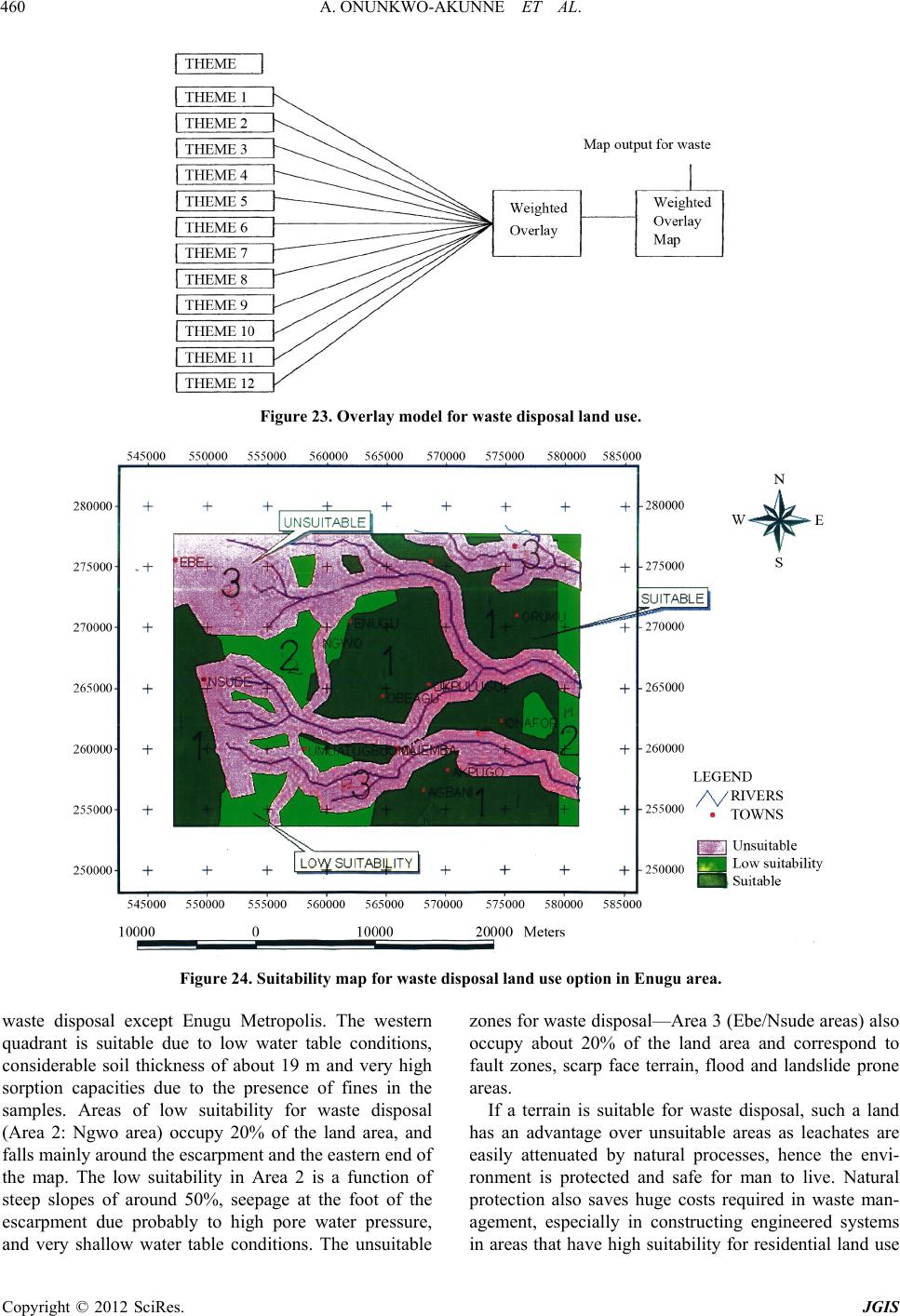 A. ONUNKWO-AKUNNE ET AL. Copyright © 2012 SciRes. JGIS 460 Figure 23. Overlay model for waste disposal land use. Figure 24. Suitability map for waste disposal land use option in Enugu area. waste disposal except Enugu Metropolis. The western quadrant is suitable due to low water table conditions, considerable soil thickness of about 19 m and very high sorption capacities due to the presence of fines in the samples. Areas of low suitability for waste disposal (Area 2: Ngwo area) occupy 20% of the land area, and falls mainly around the escarpment and the eastern end of the map. The low suitability in Area 2 is a function of steep slopes of around 50%, seepage at the foot of the escarpment due probably to high pore water pressure, and very shallow water table conditions. The unsuitable zones for waste disposal—Area 3 (Ebe/Nsude areas) also occupy about 20% of the land area and correspond to fault zones, scarp face terrain, flood and landslide prone areas. If a terrain is suitable for waste disposal, such a land has an advantage over unsuitable areas as leachates are easily attenuated by natural processes, hence the envi- ronment is protected and safe for man to live. Natural protection also saves huge costs required in waste man- agement, especially in constructing engineered systems in areas that have high suitability for residential land use 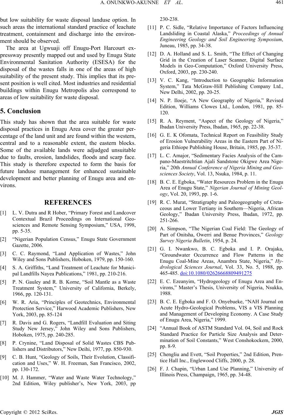 A. ONUNKWO-AKUNNE ET AL. 461 but low suitability for waste disposal landuse option. In such areas the international standard practice of leachate treatment, containment and discharge into the environ- ment should be observed. The area at Ugwuaji off Enugu-Port Harcourt ex- pressway presently mapped out and used by Enugu State Environmental Sanitation Authority (ESESA) for the disposal of the wastes falls in one of the areas of high suitability of the present study. This implies that its pre- sent position is well cited. Most industries and residential buildings within Enugu Metropolis also correspond to areas of low suitability for waste disposal. 5. Conclusion This study has shown that the area suitable for waste disposal practices in Enugu Area cover the greater per- centage of the land unit and are found within the western, central and to a reasonable extent, the eastern blocks. Some of the available lands were adjudged unsuitable due to faults, erosion, landslides, floods and scarp face. This study is therefore expected to form the basis for future landuse management for enhanced sustainable development and better planning of Enugu area and en- virons. REFERENCES [1] L. V. Dutra and R Hober, “Primary Forest and Landcover Contextual Brazil Proceedings on International Geo- sciences and Remote Sensing Symposium,” USA, 1998, pp. 5-35. [2] “Nigerian Population Census,” Enugu State Government Gazette, 2006. [3] C. C. Raymond, “Land Application of Wastes,” John Wiley and Sons Publishers, Hoboken, 1979, pp. 150-160. [4] S. A. Griffiths, “Land Treatment of Leachate for Munici- pal Landfills Nayea Publications,” 1981, pp. 210-216. [5] P. N. Gauley and R. B. Korne, “Soil Mantle as a Waste Treatment System,” University of California, Berkely, 1966, pp. 120-131. [6] W. R. Aria, “Principles of Geotechnics, Environmental Protection Service,” Harwood Academic Publishers, New York, 2003, pp. 85-124 [7] R. Davis and G. Rogers, “Landfill Evaluation and Siting Study New Jersey,” John Wiley and Sons Publishers, Hoboken, 1975, pp. 240-285. [8] P. Crynine, “Land Disposal of Solid Wastes CBS Pub- lishers and Distributors,” New Deihi, 1977, pp. 850-930. [9] C. B. Hunt, “Geology of Soils, Their Evolution, Classifi- cation and Uses,” W. H. Freeman, San Francisco, 2002, pp. 130-172. [10] M. J. Hammer, “Water and Waste Water Technology,” 2nd Edition, Wiley publisher’s, New York, 2003, pp 230-238. [11] P. C. Sidle, “Relative Importance of Factors Influencing Landsliding in Coastal Alaska,” Proceedings of Annual Engineering Geology and Soil Engineering Symposium, Juneau, 1985, pp. 34-38. [12] D. A. Holland and S. L. Smith, “The Effect of Changing Grid in the Creation of Laser Scanner, Digital Surface Models in Geo-Computation,” Oxford University Press, Oxford, 2003, pp. 230-240. [13] V. C. Kang, “Introduction to Geographic Information System,” Tata McGraw-Hill Publishing Company Ltd., New Delhi, 2002, pp. 20-25. [14] N. P. Iloeje, “A New Geography of Nigeria,” Revised Edition, Williams Clowes Ltd., London, 1981, pp. 85- 120. [15] R. A. Reyment, “Aspect of the Geology of Nigeria,” Ibadan University Press, Ibadan, 1965, pp. 22-38. [16] G. E. K Ofomata, Technical Report on Feasibility Study of Erosion Vulnerability Areas in the Eastern Part of Ni- geria Ethiope Publishing House, Britain, 1985, pp. 35-37. [17] L. C. Amajor, “Sedimentary Facies Analysis of the Cam- pano-Maestritchtian Ajali Sandstone Okigwe Area Nige- ria,” 20th Annual Conference of Nigeria Mining and Geo- sciences Society, Vol. 13, Nsuka, 1984, p. 11. [18] B. C. E. Egboka, “Water Resources Problem in the Enugu Area of Enugu State,” Nigerian Journal of Mining Geol- ogy, Vol. 20, 1993, pp. 1-6. [19] R. C. Murat, “Stratigraphy and Paleogeography of Creta- ceous and Lower Tertiany in Southern—Nigeria, African Geology,” Ibadan University Press, Ibadan, 1972, pp. 251-266. [20] A. Simpson, “The Nigerian Coal Field: The Geology of Part of Onitsha, Owerri and Benue Provinces,” Geology Survey Nigeria Bulletin, 1954, p. 24. [21] G. I. Nwankwo, B. C. Egboka and I. P. Orajaka, “Groundwater Occurrence and Flow Patterns in the Enugu Coal-Mine Areas, Anambra State, Nigeria,” Hy- drological Sciences Journal, Vol. 33, No. 5, 1988, pp. 465-485. doi:10.1080/02626668809491275 [22] E. C. Ezeanyim, “Hydrogeology of Enugu Area and En- virons,” Master’s Thesis, University of Nigeria, Nsukka, 1988. [23] B. C. E. Egboka and F. O. Onyebueke, “NAH Journal on Acute Hydro-Geological Problems, VIS a VIS Planning and Management of Developing Economy. A Case Study of Enugu Area, Nigeria,” 1999. [24] “Annual Book of ASTM Standard Vol. 04, Soil and Rock Standard Practice for Particle Size Analysis and Deter- mination of Soil Constants,” West Conshokockem, 2000, pp. 8-9. [25] Chengliu and Evett, “Soil Properties,” 2nd Edition, Pren- tice Hall Inc., Englewood Cliffs, 2000, p. 28. [26] F. J. Chapin, “Urban Land Use Planning,” University of Illinois Press, Champaign, 1965, pp. 34-48. Copyright © 2012 SciRes. JGIS |