

Paper Menu >>
Journal Menu >>
 Journal of Minerals and Materials Characterization and Engineering, 2012, 11, 1012-1019 Published Online October 2012 (http://www.SciRP.org/journal/jmmce) Electrochemical Impedance Spectroscopy of Hybrid Epoxy Resin Emulsion Coatings Rakesh N. Patil, Brihbihari V. Sharma, Prakash A. Mahanwar Department of Polymer & Surface Engineering, Institute of Chemical Technology, Mumbai, India Email: [email protected] Received May 9, 2012; revised June 13, 2012; accepted June 25, 2012 ABSTRACT A hybrid epoxy resin one pack emulsion with acrylate was synthesized for application in the field of corrosion protec- tion. Electrochemical impedance tests were applied to steel specimens coated with hybrid epoxy and tested after im- mersion in 3.5% NaCl solution at room temperature. Results taken from Nyquist and Bode plots as were analyzed by means of software provided with the instrument. Specimens were examined under scanning electron microscope shows a clear rupture and degradation in hybrid epoxy coating after prolonged exposer to salt solution. Keywords: Hybrid; Epoxy; Electrochemical Impedance Spectroscopy; Coatings 1. Introduction Epoxy resins have excellent characteristic property of corrosion resistance [1]. They have been used as two pack systems in combination of different curing agents as protective coatings [2]. However; they have poor or low fracture energy, high shrinkage, and show brittle beha- vior [3]. To overcome this disadvantages hybrid of epoxy resin was synthesized with acrylate monomers using emulsion polymerization technique. The hybrid can be defined as, the system synthesized from two or more par- ticipating components having superior properties then both the participants. The hybrid epoxy resin synthesized emulsion obtained was one pack system with longer shelf life. For the hybrid to be used as a protective coating, corrosion resistance properties must be satisfactory. Electrochemical Impedance Spectroscopy (EIS) has many advantages in comparison with other electroche- mical techniques. It is a non-destructive method for the evaluation of a wide range of materials, including coat- ings, anodized films and corrosion inhibitors. It can also provide detailed information of the systems under exami- nation; parameters such as corrosion rate, electroche- mical mechanisms and detection of localized corrosion. Polymer based coatings use barrier technology to protect substrates from corrosive chemicals and environments, particularly when in immersion service [4]. This paper reports, results of an investigation of the corrosion resistance of the hybrid coatings using EIS techniques. The hybrid one pack epoxy system was syn- thesized with conventional emulsion polymerization technique. The effects of coating thickness on water absorbance and ultimately on corrosion resistance were also studied. Nyquist and bode plots was analyzed to predict the corrosion performance of hybrid coatings. SEM analysis of the specimen was performed after im- mersion to get a closer view of coating degradation. 2. Experimental 2.1. Materials Diglycidyl ethers of bisphenol A (DGEBA) epoxy resin (D.E.R. 336) Kindly provided by Dow Chemical inter- national, India. n-butylacrylate (BA) and methylmetha- crylate (MMA) were used as the acrylic monomers. Acrylic acid (AA) and 2-hydroxyl ethyl methacrylate (HEMA) were used as the functional acrylic monomers purchased from Indofil chemicals, Potassium persulfate (KPS) used as initiator, Ethylene diamine (EDA) solution used for neutralisation and sodium bicarbonate (SBC) as a buffer was purchased from Sigma Aldrich, Nonyl phe- noxy polyethyleneoxy ethanol nonionic surfactant HLB 17.8 (Neoigen DK X 405) nonionic surfactant and sodium dodecyl benzene sulfonate (Daninol 25P) were used as anionic surfactant supplied by Dai-Ichi Karkaria. Dis- tilled and Deionized water was used throughout all experiments arranged here. All the other chemicals used in this work were AR grades obtained from a S.D. Fines Chemicals used without further purification. 2.2. Preparation of Hybrid Epoxy Resin Emulsion The synthesis of hybrid emulsion was carried out in a Copyright © 2012 SciRes. JMMCE 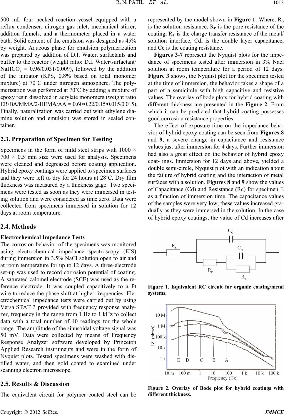 R. N. PATIL ET AL. 1013 500 mL four necked reaction vessel equipped with a reflux condenser, nitrogen gas inlet, mechanical stirrer, addition funnels, and a thermometer placed in a water bath. Solid content of the emulsion was designed as 45% by weight. Aqueous phase for emulsion polymerization was prepared by addition of D.I. Water, surfactants and buffer to the reactor (weight ratio: D.I. Water/surfactant/ NaHCO3 = 0.96/0.031/0.009), followed by the addition of the initiator (KPS, 0.8% based on total monomer mixture) at 70˚C under nitrogen atmosphere. The poly- merization was performed at 70˚C by adding a mixture of epoxy resin dissolved in acrylate monomers (weight ratio: ER/BA/MMA/2-HEMA/AA = 0.60/0.22/0.15/0.015/0.015). Finally, naturalization was carried out with ethylene dia- mine solution and emulsion was stored in sealed con- tainer. 2.3. Preparation of Specimen for Testing Specimens in the form of mild steel strips with 1000 × 700 × 0.5 mm size were used for analysis. Specimens were cleaned and degreased before coating application. Hybrid epoxy coatings were applied to specimen surfaces and they were left to dry for 24 hours at 28˚C. Dry film thickness was measured by a thickness gage. Two speci- mens were tested as soon as they were immersed in test- ing solution and were considered as time zero. Data were collected from specimens immersed in solution for 12 days at room temperature. 2.4. Methods Electrochemical Impedance Tests The corrosion behavior of the specimens was monitored using electrochemical impedance spectroscopy (EIS) during immersion in 3.5% NaCl solution open to air and at room temperature for up to 12 days. A three-electrode set-up was used to record corrosion potential of coating. A saturated calomel electrode (SCE) was used as the re- ference electrode. It was coupled capacitively to a Pt wire to reduce the phase shift at higher frequencies. Ele- ctrochemical impedance tests were carried out by using Versa STAT 3 provided with frequency response analy- zer, frequency in the range from 1 Hz to 1 kHz to collect data with a total number of 40 readings for the whole range. The amplitude of the sinusoidal voltage signal was 50 mV. Data were collected by means of Frequency Response Analyzer software developed by Princeton Applied Research instruments and were in the form of Nyquist plots. Tested specimens were washed with dis- tilled water, and then gold coated to examined under scanning electron microscope. 2.5. Results & Discussion The equivalent circuit for polymer coated steel can be represented by the model shown in Figure 1. Where, RS is the solution resistance, RP is the pore resistance of the coating, RT is the charge transfer resistance of the metal/ solution interface, Cdl is the double layer capacitance, and Cc is the coating resistance. Figures 3-7 represent the Nyquist plots for the impe- dance of specimens tested after immersion in 3% Nacl solution at room temperature for a period of 12 days. Figure 3 shows, the Nyquist plot for the specimen tested at the time of immersion, the behavior takes a shape of a part of a semicircle with high capacitive and resistive values. The overlay of bode plots for hybrid coating with different thickness are presented in the Figure 2. From which it can be predicted that hybrid coating possesses good corrosion resistance properties. The effect of exposure time on the impedance beha- vior of hybrid epoxy coating can be seen from Figures 8 and 9, a severe change in capacitance and resistance values just after immersion for 4 days. Further immersion had also a great effect on the behavior of hybrid epoxy coat- ings. Immersion for 12 days and above, yielded a double semi-circle, Nyquist plot with an indication about the failure of hybrid coating and the interaction of metal surfaces with a solution. Figures 8 and 9 show the values of Capacitance (Cd) and Resistance (Rc) for specimen E as a function of immersion time. The capacitance values of the samples were very low, these values increased gra- dually as they were immersed in the solution. In the case of hybrid epoxy coatings, the value of Cd increases after Figure 1. Equivalent RC circuit for organic coating/metal systems. Figure 2. Overlay of Bode plot for hybrid coatings with different thickness. Copyright © 2012 SciRes. JMMCE 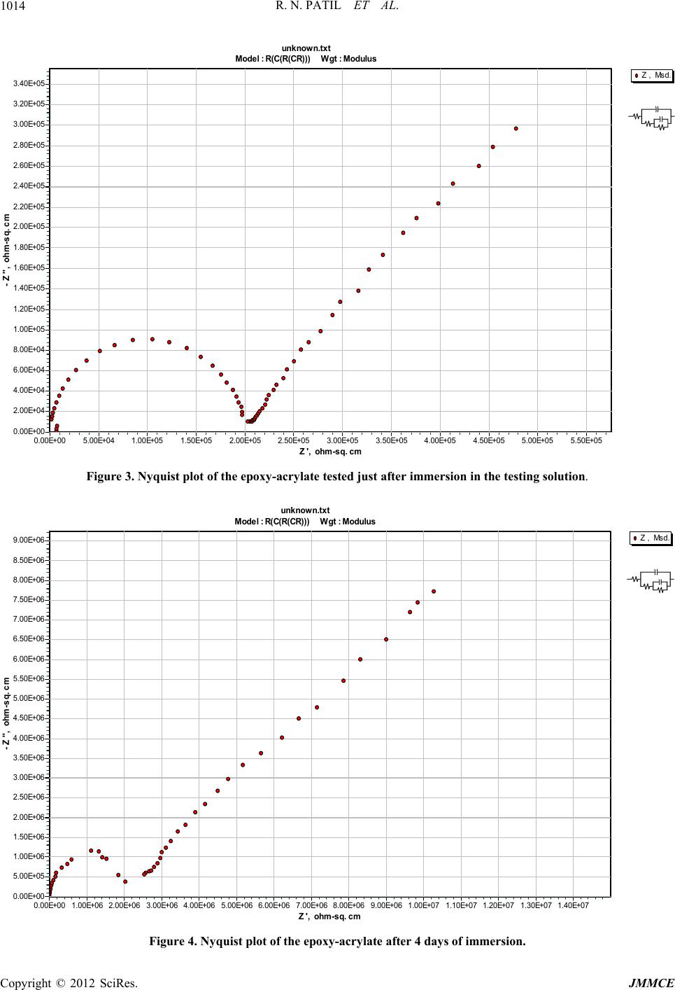 R. N. PATIL ET AL. Copyright © 2012 SciRes. JMMCE 1014 Z , Msd. unknown.txt Model : R(C(R(CR))) Wgt : Modulus Z ', ohm-sq. cm 5.50E+055.00E+054.50E+054.00E+053.50E+053.00E+052.50E+052.00E+051.50E+051.00E+055.00E+040.00E+00 - Z '', ohm-sq. cm 3.40E+05 3.20E+05 3.00E+05 2.80E+05 2.60E+05 2.40E+05 2.20E+05 2.00E+05 1.80E+05 1.60E+05 1.40E+05 1.20E+05 1.00E+05 8.00E+04 6.00E+04 4.00E+04 2.00E+04 0.00E+00 Figure 3. Nyquist plot of the epoxy-acrylate tested just after immersion in the testing solution. Z , Msd. unknown.txt Model : R(C(R(CR ))) Wgt : Modulus Z ', ohm-sq. cm 1.40E+071.30E+071.20E+071.10E+071.00E+079.00E+068.00E+067.00E+066.00E+065.00E+064.00E+063.00E+062.00E+061.00E+060.00E+00 - Z '', ohm-sq. cm 9.00E+06 8.50E+06 8.00E+06 7.50E+06 7.00E+06 6.50E+06 6.00E+06 5.50E+06 5.00E+06 4.50E+06 4.00E+06 3.50E+06 3.00E+06 2.50E+06 2.00E+06 1.50E+06 1.00E+06 5.00E+05 0.00E+00 Figure 4. Nyquist plot of the epoxy-acrylate after 4 days of immersion. 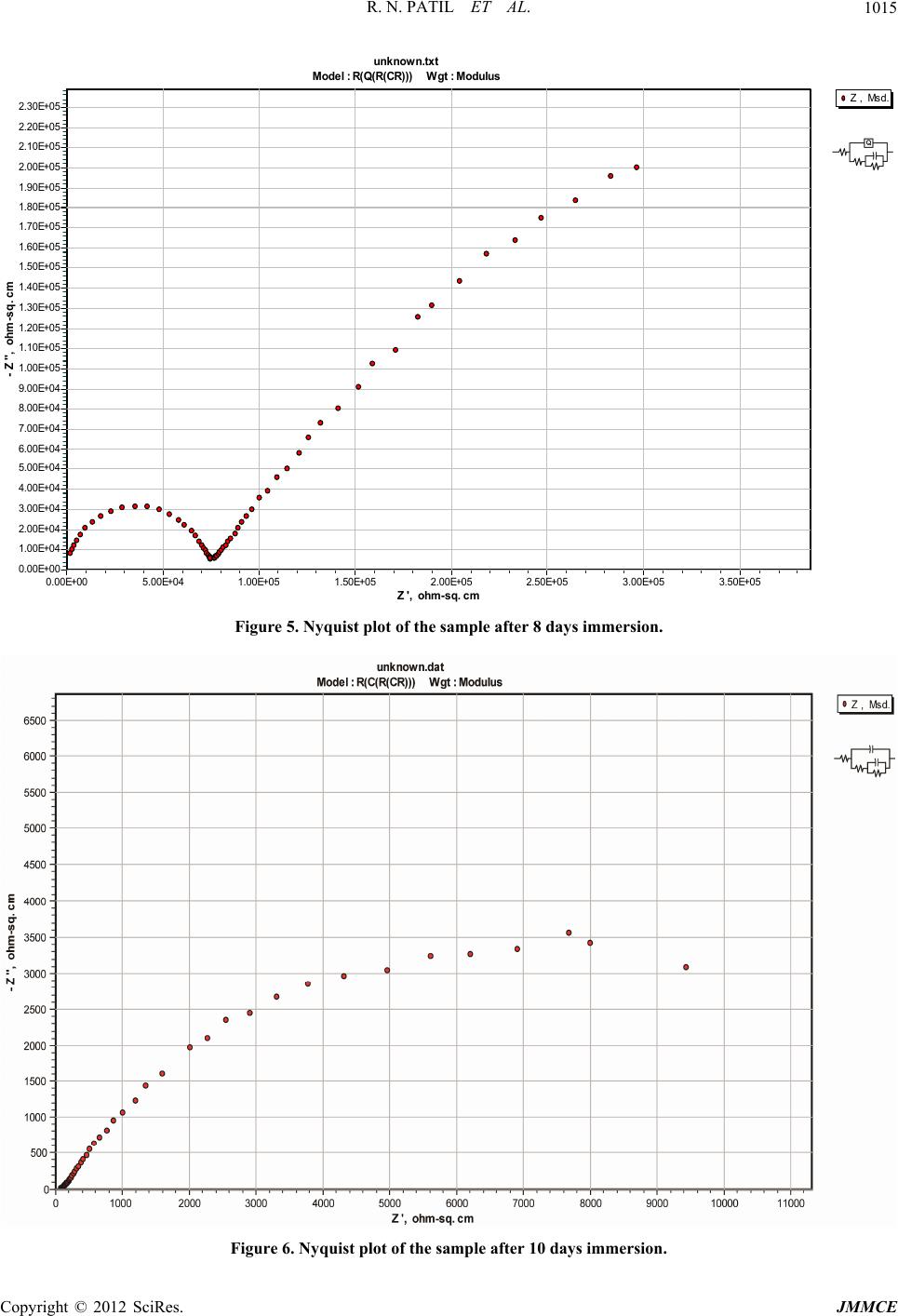 R. N. PATIL ET AL. 1015 Z , Msd. unknown.txt Model : R(Q(R(CR ))) Wgt : Modulus Z ', ohm-sq. cm 3.50E+053.00E+052.50E+052.00E+051.50E+051.00E+055.00E+040.00E+00 - Z '', ohm-sq. cm 2.30E+05 2.20E+05 2.10E+05 2.00E+05 1.90E+05 1.80E+05 1.70E+05 1.60E+05 1.50E+05 1.40E+05 1.30E+05 1.20E+05 1.10E+05 1.00E+05 9.00E+04 8.00E+04 7.00E+04 6.00E+04 5.00E+04 4.00E+04 3.00E+04 2.00E+04 1.00E+04 0.00E+00 Figure 5. Nyquist plot of the sample after 8 days immersion. Figure 6. Nyquist plot of the sample after 10 days immersion. Copyright © 2012 SciRes. JMMCE 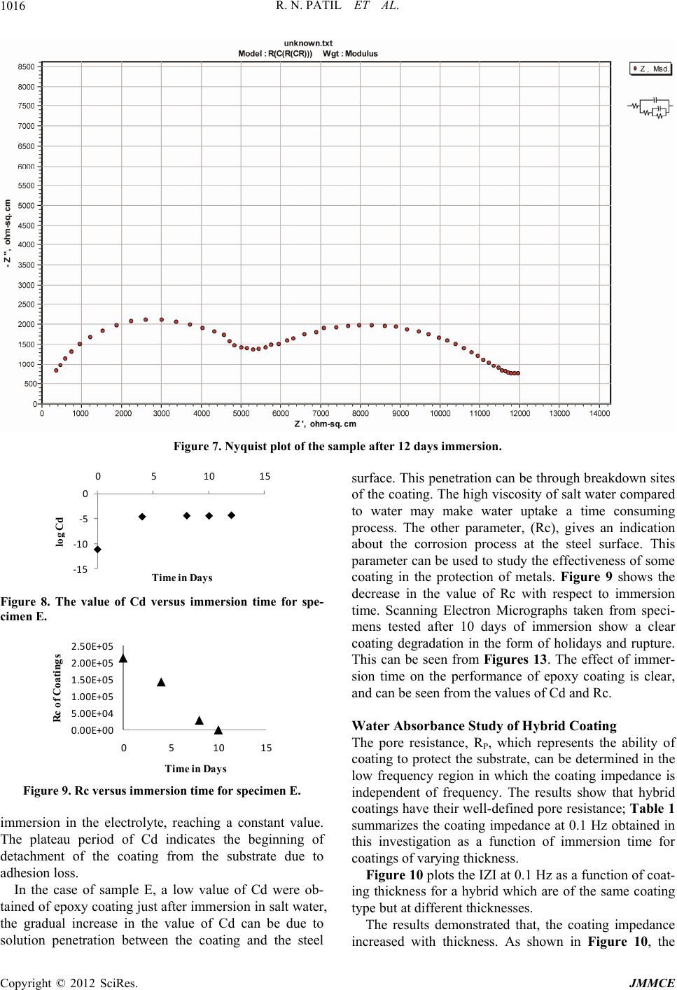 R. N. PATIL ET AL. Copyright © 2012 SciRes. JMMCE 1016 Figure 7. Nyquist plot of the sample after 12 days immersion. ‐15 ‐10 ‐5 0 0510 log Cd Time in Days 15 surface. This penetration can be through breakdown sites of the coating. The high viscosity of salt water compared to water may make water uptake a time consuming process. The other parameter, (Rc), gives an indication about the corrosion process at the steel surface. This parameter can be used to study the effectiveness of some coating in the protection of metals. Figure 9 shows the decrease in the value of Rc with respect to immersion time. Scanning Electron Micrographs taken from speci- mens tested after 10 days of immersion show a clear coating degradation in the form of holidays and rupture. This can be seen from Figures 13. The effect of immer- sion time on the performance of epoxy coating is clear, and can be seen from the values of Cd and Rc. Figure 8. The value of Cd versus immersion time for spe- cimen E. 0.00E+00 5.00E+04 1.00E+05 1.50E+05 2.00E+05 2.50E+05 0510 15 Rc of Coatings Time in Da y s Water Absorbance Study of Hybrid Coating The pore resistance, RP, which represents the ability of coating to protect the substrate, can be determined in the low frequency region in which the coating impedance is independent of frequency. The results show that hybrid coatings have their well-defined pore resistance; Table 1 summarizes the coating impedance at 0.1 Hz obtained in this investigation as a function of immersion time for coatings of varying thickness. Figure 9. Rc versus immersion time for specimen E. immersion in the electrolyte, reaching a constant value. The plateau period of Cd indicates the beginning of detachment of the coating from the substrate due to adhesion loss. Figure 10 plots the IZI at 0.1 Hz as a function of coat- ing thickness for a hybrid which are of the same coating type but at different thicknesses. In the case of sample E, a low value of Cd were ob- tained of epoxy coating just after immersion in salt water, the gradual increase in the value of Cd can be due to solution penetration between the coating and the steel The results demonstrated that, the coating impedance increased with thickness. As shown in Figure 10, the 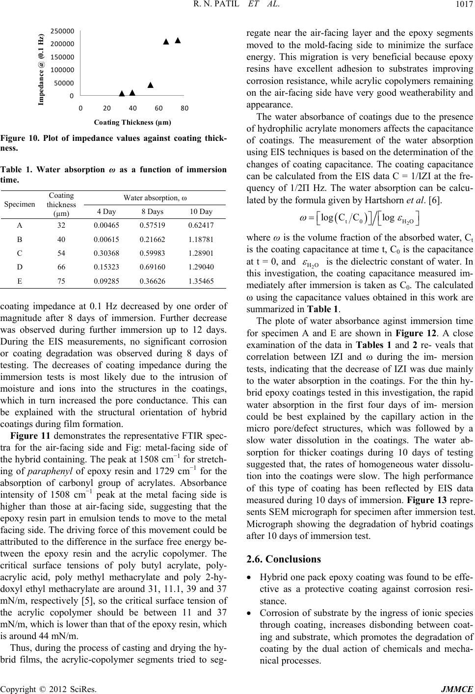 R. N. PATIL ET AL. 1017 0 50000 100000 150000 200000 250000 0 2040608 Impedance @ (0.1 Hz) Coating Thickness (µm) 0 Figure 10. Plot of impedance values against coating thick- ness. Table 1. Water absorption ω as a function of immersion time. Water absorption, ω Specimen Coating thickness (µm) 4 Day 8 Days 10 Day A 32 0.00465 0.57519 0.62417 B 40 0.00615 0.21662 1.18781 C 54 0.30368 0.59983 1.28901 D 66 0.15323 0.69160 1.29040 E 75 0.09285 0.36626 1.35465 coating impedance at 0.1 Hz decreased by one order of magnitude after 8 days of immersion. Further decrease was observed during further immersion up to 12 days. During the EIS measurements, no significant corrosion or coating degradation was observed during 8 days of testing. The decreases of coating impedance during the immersion tests is most likely due to the intrusion of moisture and ions into the structures in the coatings, which in turn increased the pore conductance. This can be explained with the structural orientation of hybrid coatings during film formation. Figure 11 demonstrates the representative FTIR spec- tra for the air-facing side and Fig: metal-facing side of the hybrid containing. The peak at 1508 cm−1 for stretch- ing of paraphenyl of epoxy resin and 1729 cm−1 for the absorption of carbonyl group of acrylates. Absorbance intensity of 1508 cm−1 peak at the metal facing side is higher than those at air-facing side, suggesting that the epoxy resin part in emulsion tends to move to the metal facing side. The driving force of this movement could be attributed to the difference in the surface free energy be- tween the epoxy resin and the acrylic copolymer. The critical surface tensions of poly butyl acrylate, poly- acrylic acid, poly methyl methacrylate and poly 2-hy- doxyl ethyl methacrylate are around 31, 11.1, 39 and 37 mN/m, respectively [5], so the critical surface tension of the acrylic copolymer should be between 11 and 37 mN/m, which is lower than that of the epoxy resin, which is around 44 mN/m. Thus, during the process of casting and drying the hy- brid films, the acrylic-copolymer segments tried to seg- regate near the air-facing layer and the epoxy segments moved to the mold-facing side to minimize the surface energy. This migration is very beneficial because epoxy resins have excellent adhesion to substrates improving corrosion resistance, while acrylic copolymers remaining on the air-facing side have very good weatherability and appearance. The water absorbance of coatings due to the presence of hydrophilic acrylate monomers affects the capacitance of coatings. The measurement of the water absorption using EIS techniques is based on the determination of the changes of coating capacitance. The coating capacitance can be calculated from the EIS data C = 1/IZI at the fre- quency of 1/2Π Hz. The water absorption can be calcu- lated by the formula given by Hartshorn et al. [6]. 2 t0 HO logCClog where ω is the volume fraction of the absorbed water, Ct is the coating capacitance at time t, C0 is the capacitance at t = 0, and 2 HO is the dielectric constant of water. In this investigation, the coating capacitance measured im- mediately after immersion is taken as C0. The calculated ω using the capacitance values obtained in this work are summarized in Table 1. The plote of water absorbance aginst immersion time for specimen A and E are shown in Figure 12. A close examination of the data in Tables 1 and 2 re- veals that correlation between IZI and ω during the im- mersion tests, indicating that the decrease of IZI was due mainly to the water absorption in the coatings. For the thin hy- brid epoxy coatings tested in this investigation, the rapid water absorption in the first four days of im- mersion could be best explained by the capillary action in the micro pore/defect structures, which was followed by a slow water dissolution in the coatings. The water ab- sorption for thicker coatings during 10 days of testing suggested that, the rates of homogeneous water dissolu- tion into the coatings were slow. The high performance of this type of coating has been reflected by EIS data measured during 10 days of immersion. Figure 13 repre- sents SEM micrograph for specimen after immersion test. Micrograph showing the degradation of hybrid coatings after 10 days of immersion test. 2.6. Conclusions Hybrid one pack epoxy coating was found to be effe- ctive as a protective coating against corrosion resi- stance. Corrosion of substrate by the ingress of ionic species through coating, increases disbonding between coat- ing and substrate, which promotes the degradation of coating by the dual action of chemicals and mecha- nical processes. Copyright © 2012 SciRes. JMMCE 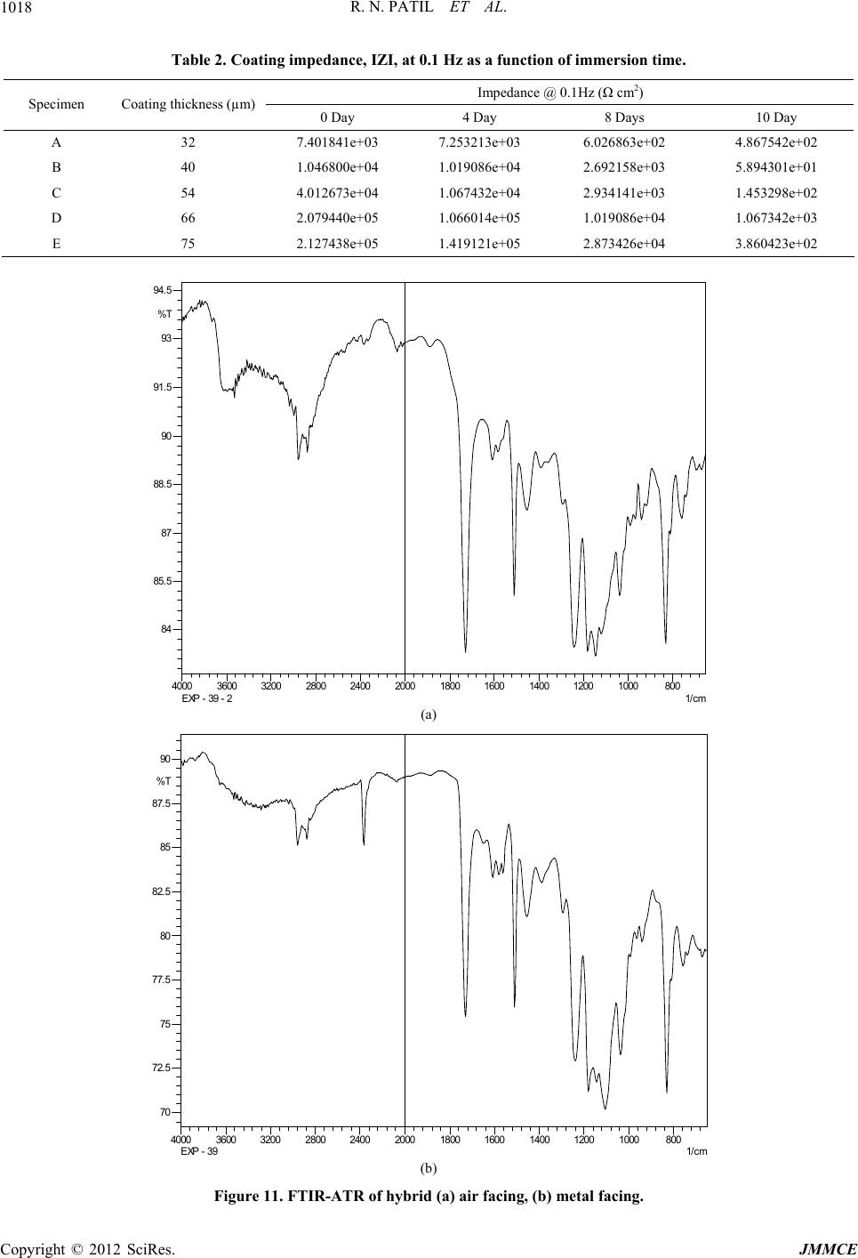 R. N. PATIL ET AL. Copyright © 2012 SciRes. JMMCE 1018 Table 2. Coating impedance, IZI, at 0.1 Hz as a function of immersion time. Impedance @ 0.1Hz (Ω cm2) Specimen Coating thickness (µm) 0 Day 4 Day 8 Days 10 Day A 32 7.401841e+03 7.253213e+03 6.026863e+02 4.867542e+02 B 40 1.046800e+04 1.019086e+04 2.692158e+03 5.894301e+01 C 54 4.012673e+04 1.067432e+04 2.934141e+03 1.453298e+02 D 66 2.079440e+05 1.066014e+05 1.019086e+04 1.067342e+03 E 75 2.127438e+05 1.419121e+05 2.873426e+04 3.860423e+02 80010001200140016001800200024002800320036004000 1/cm 84 85. 5 87 88. 5 90 91. 5 93 94. 5 %T EXP - 39 - 2 (a) 80010001200140016001800200024002800320036004000 1/cm 70 72.5 75 77.5 80 82.5 85 87.5 90 %T EXP - 39 (b) Figure 11. FTIR-ATR of hybrid (a) air facing, (b) metal facing. 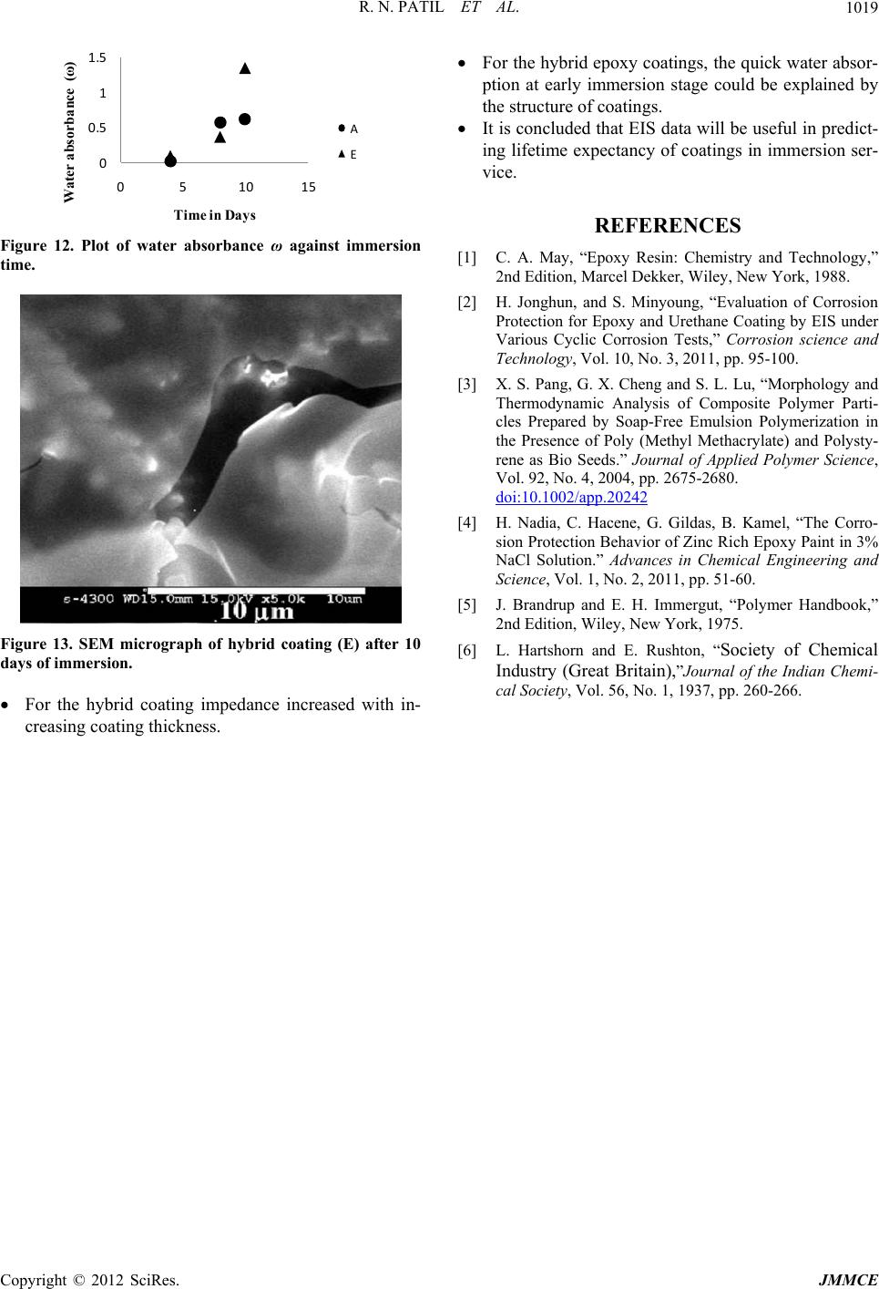 R. N. PATIL ET AL. 1019 0 0.5 1 1.5 0510 15 Water absorbance (ω) Time in Days A E Figure 12. Plot of water absorbance ω against immersion time. Figure 13. SEM micrograph of hybrid coating (E) after 10 days of immersion. For the hybrid coating impedance increased with in- creasing coating thickness. For the hybrid epoxy coatings, the quick water absor- ption at early immersion stage could be explained by the structure of coatings. It is concluded that EIS data will be useful in predict- ing lifetime expectancy of coatings in immersion ser- vice. REFERENCES [1] C. A. May, “Epoxy Resin: Chemistry and Technology,” 2nd Edition, Marcel Dekker, Wiley, New York, 1988. [2] H. Jonghun, and S. Minyoung, “Evaluation of Corrosion Protection for Epoxy and Urethane Coating by EIS under Various Cyclic Corrosion Tests,” Corrosion science and Technology, Vol. 10, No. 3, 2011, pp. 95-100. [3] X. S. Pang, G. X. Cheng and S. L. Lu, “Morphology and Thermodynamic Analysis of Composite Polymer Parti- cles Prepared by Soap-Free Emulsion Polymerization in the Presence of Poly (Methyl Methacrylate) and Polysty- rene as Bio Seeds.” Journal of Applied Polymer Science, Vol. 92, No. 4, 2004, pp. 2675-2680. doi:10.1002/app.20242 [4] H. Nadia, C. Hacene, G. Gildas, B. Kamel, “The Corro- sion Protection Behavior of Zinc Rich Epoxy Paint in 3% NaCl Solution.” Advances in Chemical Engineering and Science, Vol. 1, No. 2, 2011, pp. 51-60. [5] J. Brandrup and E. H. Immergut, “Polymer Handbook,” 2nd Edition, Wiley, New York, 1975. [6] L. Hartshorn and E. Rushton, “Society of Chemical Industry (Great Britain),”Journal of the Indian Chemi- cal Society, Vol. 56, No. 1, 1937, pp. 260-266. Copyright © 2012 SciRes. JMMCE |