

Paper Menu >>
Journal Menu >>
 Journal of Minerals and Materials Characterization and Engineering, 2012, 11, 1000-1004 Published Online October 2012 (http://www.SciRP.org/journal/jmmce) Weldability Assessment of Preheated Ductile Iron Microstructures Dakwa Yusufu Kwa1, Joseph Olatunde Borode2*, Itopa Monday Momoh1 1Department of Research and Development, Engineering Materials Development Institute, Akure, Nigeria 2Department of Metallurgical and Materials Engineering, Federal University of Technology-Akure, Akure, Nigeria Email: [email protected] Received August 23, 2012; revised September 27, 2012; accepted October 10, 2012 ABSTRACT When joining ductile iron by submerged arc welding technique, a suitable welding speed and current, among other fac- tors, need to be skillfully put in place so as to enhance good welding. This work is based on microstructural examina- tion of pr eheated ductile iron at v arious temperatures ran ging between 100˚C - 400 ˚C. Optical microscope was used for the microstructure analysis. The result shows varied complex microstructures at the fusion zone, un-mixed zone, par- tially melted zone and at the heat affected zone. Keywords: Submerged Arc Welding; Fusion Zone; Un-Mixed Zone; Heat Affected Zone 1. Introduction The transformation of materials to goods for the satisfac- tion of human needs is brought into a reality through manufacturing/fabrication processes. Thus, Manufactur- ing as an indisp ensable part of production can be consid - ered as a system in which product design at the initial stage is processed and delivered as finished products to the market as the final output fo r u se . Welding has become a dominant process in manufac- turing, without which a large number of products would have to be considerably modified, would be more costly, or could not perform as efficiently if it were not available. It is a process by which two materials are permanently joined together by coalescence, which is induced by a combination of temperature pressure and some other metallurgical conditions. An atomic bonding configura- tion is formed having a natural election configuration be- tween the two materials by bringing their surfaces to- gether [1]. The ideal weld bond requires a perfectly smooth, flat or matching surface, clean surfaces free from contaminants, materials with no internal impurities, materials that are both single crystals with identical crys- tallographic structure and orientation. These conditions are impossible to achieve in practice, thus, various weld- ing processes have been developed and preparation de- signs have been developed to compensate for the imper- fection. In solid state welding processes, contaminated layers are removed by mechanical or chemical action prior to welding, or by forcing the metal to flow along the inter- face so that impurities are squeezed out. In fusion weld- ing, fluxing agents are used to remove contaminants from the pool of molten metal formed during the welding op- eration. Welding in a vacuum also prevents contamina- tion and promotes the removal of contaminants. Coales- cence, therefore, occurs with considerable ease. A high quality weld therefore requires a source of sat- isfactory heat and pressure, a means of cleaning and keeping the material free from contamination, and pre- cautions to compensate for, or avoid harmful metallurgi- cal effects. The development of commercial industries in the late 19th and 20th century, in addition to lessons learnt by ca- tastrophic engineering failures that occurred in that pe- riod, brought abou t a great understanding of the im- por- tance of welding and weld quality. Fusion welding proc- esses were rapidly developed and improved upon [2]. High amount of carbon, silicon [3] with combination of other elements increases the carbon equivalent of cast iron. High carbon equivalent decreases cast iron’s weld- ability. The objective of improving weldability may be achieved by either preheating, or heat treatment, or both. Ductile iron is one of the numerous ferrous materials that has its applications both at room temperature and at elevated temperatures. The majority of the reported dete- rioration in high temperature operating components are microstructural degradation [4,5], hydrogen damage, gra- phitization, thermal shock, erosion, liquid metal embrit- tlement, and high temperature corrosion of various types [5]. *Corresponding author. Copyright © 2012 SciRes. JMMCE 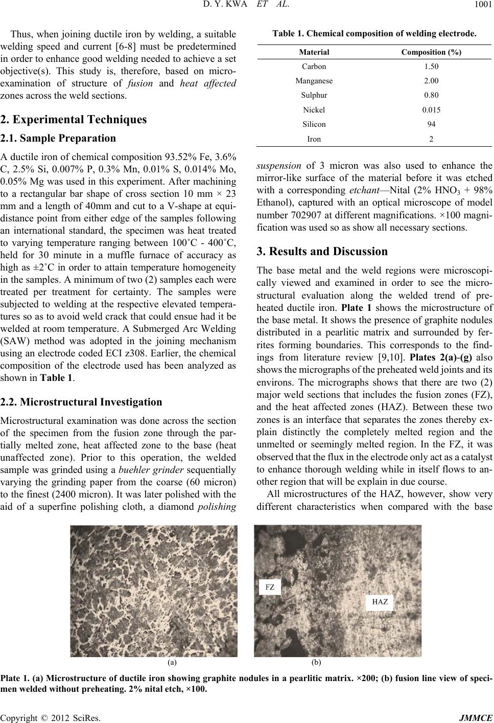 D. Y. KWA ET AL. 1001 Thus, when joining ductile iron by welding, a suitable welding speed and current [6-8] must be predetermined in order to enhance good welding needed to achieve a set objective(s). This study is, therefore, based on micro- examination of structure of fusion and heat affected zones across the weld sections. 2. Experimental Techniques 2.1. Sample Preparation A ductile iron of chemical composition 93.52% Fe, 3.6% C, 2.5% Si, 0.007% P, 0.3% Mn, 0.01% S, 0.014% Mo, 0.05% Mg was used in this experiment. After machining to a rectangular bar shape of cross section 10 mm × 23 mm and a length of 40mm and cut to a V-shape at equi- distance point from either edge of the samples following an international standard, the specimen was heat treated to varying temperature ranging between 100˚C - 400˚C, held for 30 minute in a muffle furnace of accuracy as high as ±2˚C in order to attain temperature homogeneity in the samples. A minimum of two (2) samples each were treated per treatment for certainty. The samples were subjected to welding at the respective elevated tempera- tures so as to avoid weld crack that could ensue had it be welded at room temperature. A Submerged Arc Welding (SAW) method was adopted in the joining mechanism using an electrode coded ECI z308. Earlier, the chemical composition of the electrode used has been analyzed as shown in Table 1. 2.2. Microstructural Investigation Microstructural examination was done across the section of the specimen from the fusion zone through the par- tially melted zone, heat affected zone to the base (heat unaffected zone). Prior to this operation, the welded sample was grinded using a buehler grinder sequentially varying the grinding paper from the coarse (60 micron) to the finest (2400 micron). It was later polished with the aid of a superfine polishing cloth, a diamond polishing Table 1. Chemical composition of welding electrode. Material Composition (%) Carbon 1.50 Manganese 2.00 Sulphur 0.80 Nickel 0.015 Silicon 94 Iron 2 suspension of 3 micron was also used to enhance the mirror-like surface of the material before it was etched with a corresponding etchant—Nital (2% HNO3 + 98% Ethanol), captured with an optical microscope of model number 702907 at different magnifications. ×100 magni- fication was used so as show all necessary sections. 3. Results and Discussion The base metal and the weld regions were microscopi- cally viewed and examined in order to see the micro- structural evaluation along the welded trend of pre- heated ductile iron. Plate 1 shows the microstructure of the base metal. It shows the presence of graphite nodules distributed in a pearlitic matrix and surrounded by fer- rites forming boundaries. This corresponds to the find- ings from literature review [9,10]. Plates 2(a)-(g) also shows the micrographs of the preheated weld joints and its environs. The micrographs shows that there are two (2) major weld sections that includes the fusion zones (FZ), and the heat affected zones (HAZ). Between these two zones is an interface that separates the zones thereby ex- plain distinctly the completely melted region and the unmelted or seemingly melted region. In the FZ, it was observed that the flux in the electrode only act as a catalyst to enhance thorough welding while in itself flows to an- other region that will be explain in due course. All microstructures of the HAZ, however, show very different characteristics when compared with the base (a) (b) Plate 1. (a) Microstructure of ductile iron showing graphite nodules in a pearlitic matrix. ×200; (b) fusion line view of speci- men welded without preheating. 2% nital etch, ×100. Copyright © 2012 SciRes. JMMCE 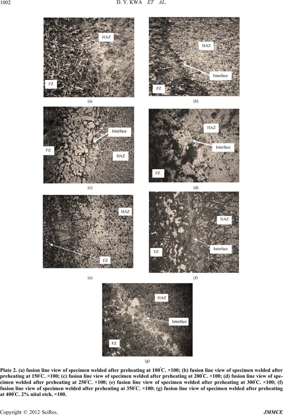 D. Y. KWA ET AL. 1002 Plate 2. (a) fusion line view of specimen welded after preheating at 100ᵒC. ×100; (b) fusion line view of specimen welded after preheating at 150ᵒC. ×100; (c) fusion line view of specimen welded after preheating at 200ᵒC. ×100; (d) fusion line view of spe- cimen welded after preheating at 250ᵒC. ×100; (e) fusion line view of specimen welded after preheating at 300ᵒC. ×100; (f) fusion line view of specimen welded after preheating at 350ᵒC. ×100; (g) fusion line view of specimen welded after preheating at 400ᵒC. 2% nital etch, ×100. Copyright © 2012 SciRes. JMMCE  D. Y. KWA ET AL. Copyright © 2012 SciRes. JMMCE 1003 metal. Moving away from the fusion line, the peak tem- peratures and temperature gradients get lower. Cooling rates are also lower because of the lower temperature gradients. Varied Structures were, thus, formed. 3.1. Un-Mixed Zone (UMZ) The distinct regions in the HAZ can be determined as unmixed zone (UMZ), partially melted zone (PMZ), and true heat affected zone (HAZ). In the HAZ only phase transformations take place. No melting takes place as it is experienced at the UMZ and PMZ. The UMZ region is a completely melted region, but mixing of filler and base metal is not achieved as the filler act as a catalyst—en- hancing welding and diffuse out to PMZ. The increased cooling rates enhance the transformation o f austenite thus preventing the precipitation of carbon in the liquid to graphite but get trappe d in iron carbide which is hard. 3.2. Partially Melted Zone (PMZ) The PMZ forms next to UMZ as a boundary to HAZ. Melting is not total in this zone. The temperature has values between the eutectic and liquids temperature of cast iron. Structures formed in this zone are mainly by carbon diffusion out of graphite nodules. At high tem- perature, the carbon is susceptible to diffusion out of the nodules increasing to concentration of carbon in the sur- rounding matrix. This continues until melting takes place. High carbon concentration in the surrounding supports eutectic melting, but the high cooling rates cause the melted matrix to transform. Further away from the gra- phite nodule, melting does not occur and martensite is formed by means of phase transformation. 3.3. Heat Affected Zone (HAZ) No melting takes place at the HAZ. As the distance away from the PMZ is increased, the temperature gradient also gets reduced. The amount of martensite, thus, gets re- duced also. The regions close to the PMZ have a marten- sitic matrix as shown in Plates 3(a)-(d). 4. Conclusions Preheating of ductile iron before welding using a SAW method results in a complex and varied multi-microstru- ctures depending on the preheating temperature and the (a) (b) (c) (d) Plate 3. (a) HAZ of section closest to the base metal in the specimen preheated to 400˚C showing increased pearlite in the ma- trix. ×400; (b) HAZ of section closest to the base metal in the specimen preheated that would otherwise have been martensite. ×200; (c) HAZ of section closest to the base metal in the specimen preheated to 250˚C. ×200; (d) HAZ closer to the PMZ of the specimen welded after preheating at 350˚C. ×200.  D. Y. KWA ET AL. 1004 temperature gradient. - At 400˚C before welding, transformation of austenite resulting in the formation of fewer hard structures in the FZ, UMZ, and PMZ, but having a high area frac- tion of the hard structures (martensite and carbides) at the HAZ was observed. - At 300˚C and 350˚C before weld ing produced a h igh- er area fraction of hard structures in the PMZ and fewer hard structures in the FZ and HAZ. - At 100˚C, 150˚C, 200˚C, and 250˚C, the microstruc- tures at the FZ formed were visually estimated to be lower and equal relative to other zones. - Preheating of ductile iron, when carried out using SAW method using ECI Z308 electrodes enhances better microstructure that could in turn enhances the mechanical properties. REFERENCES [1] R. W. Messler, “Joining of Materials and Structures from Pragmatic process to Enabling Technology,” Butter Worth Heinemann, Burlington, 2004. [2] R. Blondeau, “Metallurgy and Mechanics of Welding: Processes and Industrial Applications,” Wiley, Hoboken, 2008. [3] A. V. Adedayo and B. Aremo, “Influence of Mould Heat Storage Capacity on Properties of Grey Iron,” Journal of Minerals & Materials Characterization & Engineering, Vol. 10, No. 4, 2011, pp. 387-396. [4] C. Barbosa, J. L. Nascimento, I. M. V. Caminha and I. C. Abud, “Microstructural Aspects of the Failure Analysis of Nickel Base Superalloys Components,” Engineering Failure Analysis, Vol. 12, No. 3, 2005, pp. 348-361. doi:10.1016/j.engfailanal.2004.09.010 [5] A. M. Babakr, A. Al-Ahmari, K. Al-Jumayiah and F. Habiby, “Sigma Phase Formation and Embrittlement of Cast Iron-Chromium-Nickel (Fe-Cr-Ni) Alloys,” Journal of Minerals & Materials Characterization & Engineering, Vol. 7, No. 2, 2008, pp. 127-145. [6] E. M. El-Banna, “Effect of Preheat on Welding of Ductile Cast Iron,” Materials Letters, Vol. 4, No. 1, 1999, pp. 20-26. [7] W. L. Galvery and F. B. Marlow, “Welding Essentials,” Galvery and Marlow Industrial Press, New York, 2007, [8] H. B. Cary and S. Hetzer, “Modern Welding Technol- ogy,” Cary and Hetzer Prentice Hall, Upper Saddle River, New Jersey, 2004, [9] D. M. Viano, N. U. Ahmed and G. O. Schumann, “Influ- ence of Heat Input and Travel Speed on Microstructure and Mechanical Properties of Double Tandem Submerged Arc High Strength Low Alloy Steel Weldments,” Journal of Science and Technology of Welding and Joining, Vol. 5, No. 1, 2000, pp. 26-34. doi:10.1179/136217100322910642 [10] P. Keshav and D. K. Dwivedi, “Microstructure and Ten- sile Properties of Submerged Arc Welded 1.25Cr-0.5Mo Steel Joints,” Journal of Materials and Manufacturing Processes, Vol. 23, No. 5, 2008, pp. 463-468. doi:10.1080/10426910802103551 Copyright © 2012 SciRes. JMMCE |