

Paper Menu >>
Journal Menu >>
 Journal of Modern Physics, 2012, 3, 1697-1702 http://dx.doi.org/10.4236/jmp.2012.330208 Published Online October 2012 (http://www.SciRP.org/journal/jmp) Self Consistently Generated Charge Cylinder in BETA Device Rajwinder Kaur, A. Sarada Sree, Shiban Kishan Mattoo Institute for Plasma Research, Gandhinagar, India Email: [email protected] Received August 22, 2012; revised September 20, 2012; accepted September 27, 2012 ABSTRACT This paper presents a study on near cathode space charge region in BETA (Basic Experiments in Toroidal Assembly), a toroidal plasma device with purely toroidal magnetic field. A charge cylinder has been found to be embedded in the plasma center corresponding to the hot filament cathode location in poloidal cross section. This charge cylinder has been created by the primary electrons emitted from the filament surface, which in turn, leads to the formation of a po- tential well in the core plasma. We have proposed a model, which shows that a tiny fraction of injected energetic elec- trons is sufficient to sustain the observed potential well. We have examined the equilibrium of the charge cylinder in poloidal cross-section and found that it exhibits equilibrium configuration by forming circulation pattern of primary electrons. The circulation pattern is formed by vertical drift due to toroidal magnetic field and self-consistent poloidal E B drift. We have concluded that the self-consistency is in adjusting the poloidal drift to the vertical drift of the trapped primary electrons. Keywords: Hot Cathode Discharge; Near Cathode Space Charge; Toroidal Magnetic Field 1. Introduction The near cathode space-charge behavior is of great inter- est in plasma discharges [1-5]. These studies have at- tracted lot of interest due to their applications in plasma surface processing. Analytic and numerical models have been developed [2-5] to gain the understanding of the physical processes occurring in the cathode region of dis- charges. The knowledge of primary electron trajectories in this region helps in understanding and predicting vari- ous discharge characteristics. Three dimensional (3D) computer simulation techniques have been developed for tracking the primary electrons and applied to numerous applications [6-9]. The influence of different magnetic fields on plasma discharge has been studied by tracing the primary electron trajectories near the filament. This paper presents an experimental study on near ca- thode space charge region in a hot filament cathode dis- charge produced toroidal plasma device BETA. The plas- ma in BETA device [9-11] is produced by a hot filament cathode discharge. The hot filament cathode injects ener- getic primary electrons into the plasma. However, the observed value of the charge density is much less than the injected charge density. An anomalous radial cross- field current transports most of the injected charge [12- 15]. Only a small amount of residual space charge still exists that is responsible for the creating a charge cylin- der in plasma center with axis coinciding with the major axis of the torus. This charge cylinder in turn, sustains the observed potential well. We have examined the equi- librium of this charge cylinder and proposed a model to account for the behavior of trapped primary electrons. The paper is organized as follows. Section 2 gives an outline of experimental setup and experimental results are given in Section 3. Section 4 gives a discussion on the existence and equilibrium of the charge cylinder. Fi- nally conclusions drawn from the experimental results and discussion are given in Section 5. 2. Experimental Setup The experimental apparatus BETA device (Figure 1) consists of a toroidal vacuum chamber of major radius 45 cm and minor radius 15 cm pumped down to base pres- sure of 10−6 Torr [9-11]. A toroidal magnetic field is pro- duced by a set of 16 coils and can be varied up to 1 kG. The plasma is produced by a discharge between a cath- ode of hot filament and the vacuum vessel at a pressure of 10−4 Torr. The working gas is argon. A circular aper- ture of diameter 18 cm defines the size of the plasma. The plasma lacks equilibrium in the MHD sense. How- ever, a steady state plasma can be maintained by the bal- ance of charge production and their loss. Time averaged plasma parameters are measured using a radially mov- C opyright © 2012 SciRes. JMP 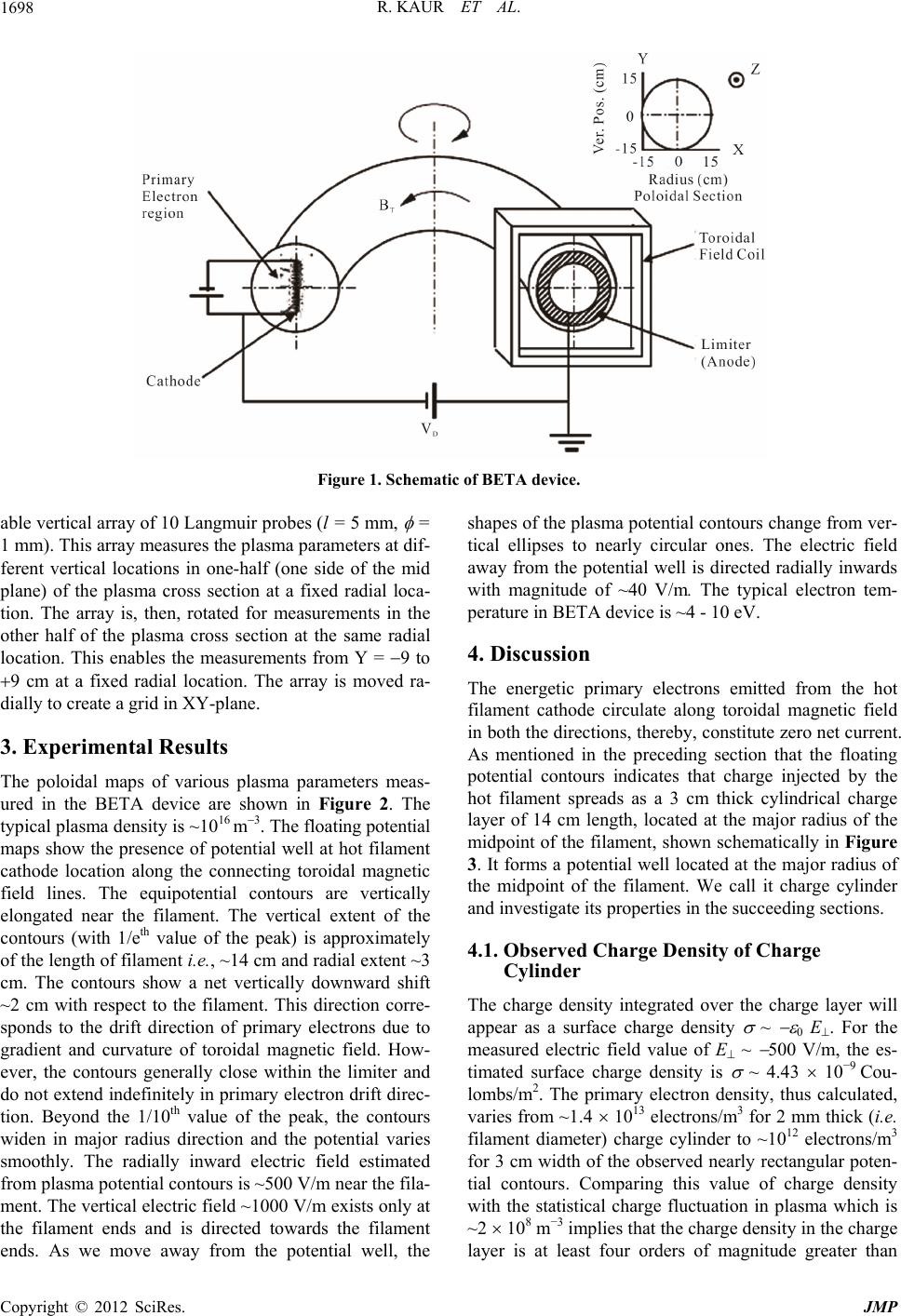 R. KAUR ET AL. 1698 Figure 1. Schematic of BETA device. able vertical array of 10 Langmuir probes (l = 5 mm, = 1 mm). This array measures the plasma parameters at dif- ferent vertical locations in one-half (one side of the mid plane) of the plasma cross section at a fixed radial loca- tion. The array is, then, rotated for measurements in the other half of the plasma cross section at the same radial location. This enables the measurements from Y = 9 to 9 cm at a fixed radial location. The array is moved ra- dially to create a grid in XY-plane. 3. Experimental Results The poloidal maps of various plasma parameters meas- ured in the BETA device are shown in Figure 2. The typical plasma density is ~1016 m3. The floating potential maps show the presence of potential well at hot filament cathode location along the connecting toroidal magnetic field lines. The equipotential contours are vertically elongated near the filament. The vertical extent of the contours (with 1/eth value of the peak) is approximately of the length of filament i.e., ~14 cm and radial extent ~3 cm. The contours show a net vertically downward shift ~2 cm with respect to the filament. This direction corre- sponds to the drift direction of primary electrons due to gradient and curvature of toroidal magnetic field. How- ever, the contours generally close within the limiter and do not extend indefinitely in primary electron drift direc- tion. Beyond the 1/10th value of the peak, the contours widen in major radius direction and the potential varies smoothly. The radially inward electric field estimated from plasma potential contours is ~500 V/m near the fila- ment. The vertical electric field ~1000 V/m exists only at the filament ends and is directed towards the filament ends. As we move away from the potential well, the shapes of the plasma potential contours change from ver- tical ellipses to nearly circular ones. The electric field away from the potential well is directed radially inwards with magnitude of ~40 V/m. The typical electron tem- perature in BETA device is ~4 - 10 eV. 4. Discussion The energetic primary electrons emitted from the hot filament cathode circulate along toroidal magnetic field in both the directions, thereby, constitute zero net current. As mentioned in the preceding section that the floating potential contours indicates that charge injected by the hot filament spreads as a 3 cm thick cylindrical charge layer of 14 cm length, located at the major radius of the midpoint of the filament, shown schematically in Figure 3. It forms a potential well located at the major radius of the midpoint of the filament. We call it charge cylinder and investigate its properties in the succeeding sections. 4.1. Observed Charge Density of Charge Cylinder The charge density integrated over the charge layer will appear as a surface charge density ~ 0 E . For the measured electric field value of E ~ 500 V/m, the es- timated surface charge density is ~ 4.43 10−9 Cou- lombs/m2. The primary electron density, thus calculated, varies from ~1.4 1013 electrons/m3 for 2 mm thick (i.e. filament diameter) charge cylinder to ~1012 electrons/m3 for 3 cm width of the observed nearly rectangular poten- tial contours. Comparing this value of charge density with the statistical charge fluctuation in plasma which is ~2 108 m−3 implies that the charge density in the charge layer is at least four orders of magnitude greater than Copyright © 2012 SciRes. JMP 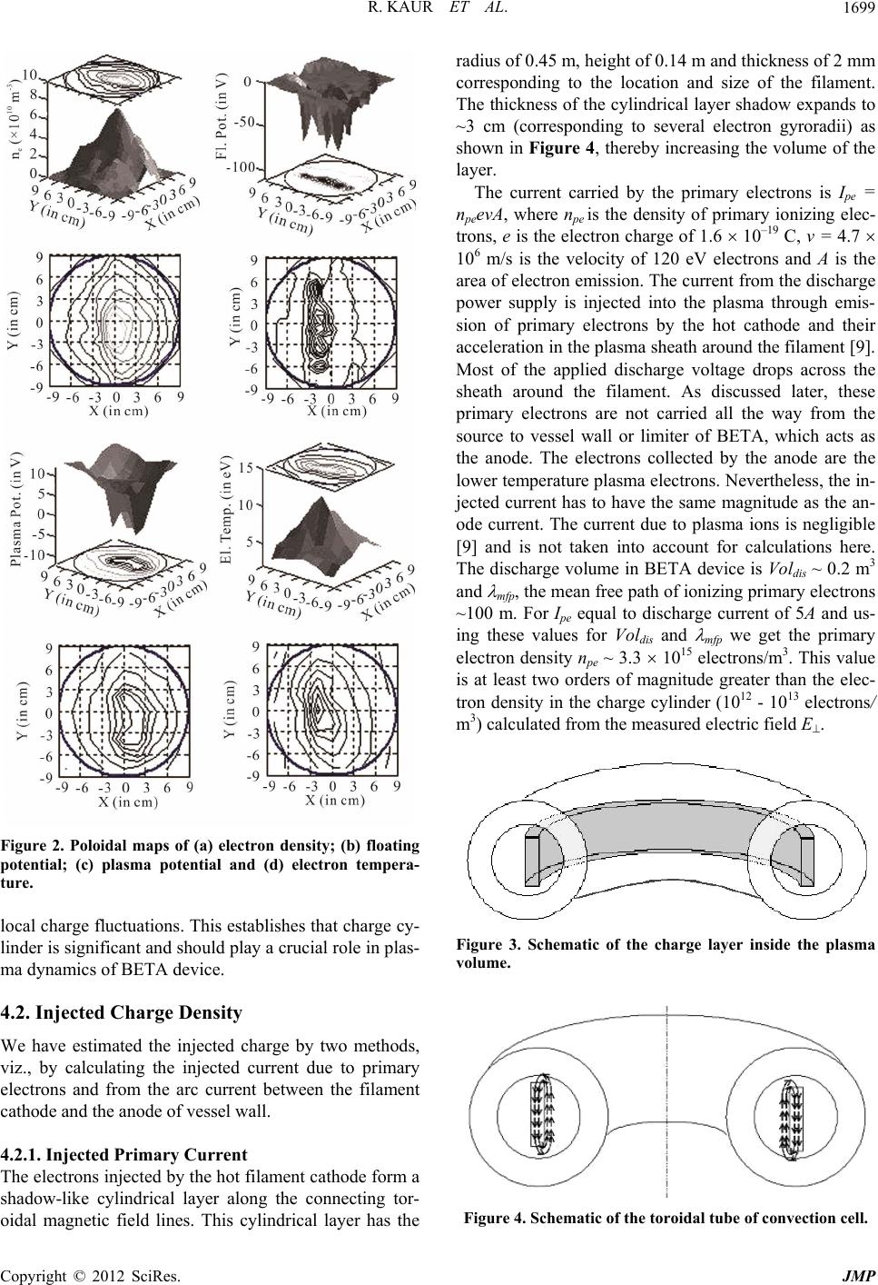 R. KAUR ET AL. 1699 Figure 2. Poloidal maps of (a) electron density; (b) floating potential; (c) plasma potential and (d) electron tempera- ture. local charge fluctuations. This establishes that charge cy- linder is significant and should play a crucial role in plas- ma dynamics of BETA device. 4.2. Injected Charge Density We have estimated the injected charge by two methods, viz., by calculating the injected current due to primary electrons and from the arc current between the filament cathode and the anode of vessel wall. 4.2.1. Injected Primary Current The electrons injected by the hot filament cathode form a shadow-like cylindrical layer along the connecting tor- oidal magnetic field lines. This cylindrical layer has the radius of 0.45 m, height of 0.14 m and thickness of 2 mm corresponding to the location and size of the filament. The thickness of the cylindrical layer shadow expands to ~3 cm (corresponding to several electron gyroradii) as shown in Figure 4, thereby increasing the volume of the layer. The current carried by the primary electrons is Ipe = npeevA, where npe is the density of primary ionizing elec- trons, e is the electron charge of 1.6 10–19 C, v = 4.7 106 m/s is the velocity of 120 eV electrons and A is the area of electron emission. The current from the discharge power supply is injected into the plasma through emis- sion of primary electrons by the hot cathode and their acceleration in the plasma sheath around the filament [9]. Most of the applied discharge voltage drops across the sheath around the filament. As discussed later, these primary electrons are not carried all the way from the source to vessel wall or limiter of BETA, which acts as the anode. The electrons collected by the anode are the lower temperature plasma electrons. Nevertheless, the in- jected current has to have the same magnitude as the an- ode current. The current due to plasma ions is negligible [9] and is not taken into account for calculations here. The discharge volume in BETA device is Voldis ~ 0.2 m3 and mfp, the mean free path of ionizing primary electrons ~100 m. For Ipe equal to discharge current of 5A and us- ing these values for Voldis and mfp we get the primary electron density npe ~ 3.3 1015 electrons/m3. This value is at least two orders of magnitude greater than the elec- tron density in the charge cylinder (1012 - 1013 electrons/ m3) calculated from the measured electric field E. Figure 3. Schematic of the charge layer inside the plasma volume. Figure 4. Schematic of the toroidal tube of convection cell. Copyright © 2012 SciRes. JMP  R. KAUR ET AL. 1700 4.2.2. Arc Current One can also estimate the number density of electrons participating in discharge current by another method. The primary electrons (injected by hot cathode) of energy ~120 eV are trapped by toroidal magnetic field although they drift due to curvature and grad B forces. It has been observed that the primary energetic electrons are not found beyond 2 cm in radial direction on the inboard and outboard sides of filament. They are also not found near the bottom side of the vessel due to downward drift. This implies that primary electrons do not reach the vessel wall of BETA. Hence, it is a good assumption to con- sider that the injected primary electrons are not directly participating in the discharge current. The functional role of primary electrons is to create ionization resulting in the formation of plasma and to excite neutral atoms of Ar. They spend the major portion of their energy through the processes of excitation of radiation levels in atoms. In BETA, it is not possible to compensate the radial current from charge cylinder to the vessel wall or limiter due to classical diffusion [12-15]. On the other hand, electron flow parallel to the toroidal magnetic field form counter streams due to two sided injection of energetic electrons on the field lines that intercept filament and therefore do not contribute to the current. The single par- ticle drifts (due to gradient and curvature of toroidal magnetic field and E B drift) are insufficient in trans- porting the charge from filament region to the vessel wall. Therefore the cross-field charge transport is carried out by an anomalous mechanism initiated by the turbulence in the plasm [12-15]. Once plasma is created, the plasma electrons carry the discharge current across the toroidal magnetic field, en- abled by anomalous perpendicular diffusion. The radial velocity of these electrons vr is ~kθ φ/B, where kθ is the poloidal wavevector of the dominant plasma fluctuations mode and φ is amplitude of its electrostatic potential. For fluctuations in BETA, the range of poloidal wavevectors [11] is –100 m−1 k 200 m−1. The value of poloidal wavevector kθ for the dominant mode is ~30 m−1. For the work reported in this paper, B = 0.02 T and φ ~ 1 V, re- sulting in radial velocity vr of ~9.4 103 m/s. We note here that vr is much less that the velocity of the injected electrons at the plasmasheath boundary around the fila- ment. For Idis = npeevrAw = 5 A and area of the vessel wall Aw = 2.7 m2, the calculated value of npe ~ 4.8 1015 elec- trons/m3. This value of primary electrons density npe is of the order of value estimated in preceding section by the method of using the injected current is due to primary electrons. Further, npe is just about 10% of the peak plasma density implying that only tail energy distribution of plasma electrons is sufficient to enable discharge cur- rent between the hot filament cathode of tungsten and the anode of vessel wall. 4.3. Resolving Discrepancy between Measured and Injected Charge Density The discrepancy between the observed primary electron density (estimated in Section 4.1) and the calculated in- jected electron density (estimated in Sections 4.2.1 & 4.2.2) in the charge cylinder implies that only a fraction of injected energetic electrons is retained as space charge of the charge cylinder. In fact, electron density in the charge cylinder is two orders of magnitude smaller than the density of injected electrons. The argument that most of the injected electrons, about 99%, are lost due to the vertical drift is not supported by the observations. It has been observed experimentally that the negative potential well has a limited spatial extent in vertical direction and is receded from the vessel wall. The loss path of primary electrons to the vessel wall, along the vertically down- ward direction due to drifts, is not observed in the ex- periments. This implies that the charge cylinder, made up of primary electrons, does exist. Therefore, if there is a massive loss of injected electrons from the charge cylin- der, it has to be by alternative processes, other than the drifts introduced by toroidal magnetic field. A reasonable explanation is that significant charge neutralization takes place as a consequence of inward ion diffusion towards the charge cylinder. This leads to significant reduction of electric field in the charge, i.e., E to 500 V/m as against the value E ~ 104 V/m for the situation when electric field is sustained by the injected charge density (esti- mated in Sections 4.2.1 & 4.2.2). 4.4. Equilibrium of Charge Cylinder We now consider the dynamics of the observed charge cylinder that is independent of interaction of primary electrons with the surrounding plasma and all pervading neutral atoms. To a large extent, charge neutralization plays a considerable role in reducing the non-neutral component of plasma and consequently the magnitude of electric field inside the charge cylinder. The interaction with neutrals is through ionization and radiation. How- ever, these interactions do not explain the existence of structure, which is isolated from the vessel wall and sus- pended in the plasma. To achieve isolation from the ves- sel wall, it is essential that the vertical drift of primary electrons is either cancelled or is converted into a pol- oidal drift at the extreme ends of the charge cylinder. Alternatively, a sink for primary electrons has to be placed at the bottom end of the cylinder. A sink is con- ceivable in terms of the filament support holders, which form a shadow region for the primary electrons. Against this hypothesis is the bias condition of these holders that are negatively biased to the same voltage as discharge Copyright © 2012 SciRes. JMP 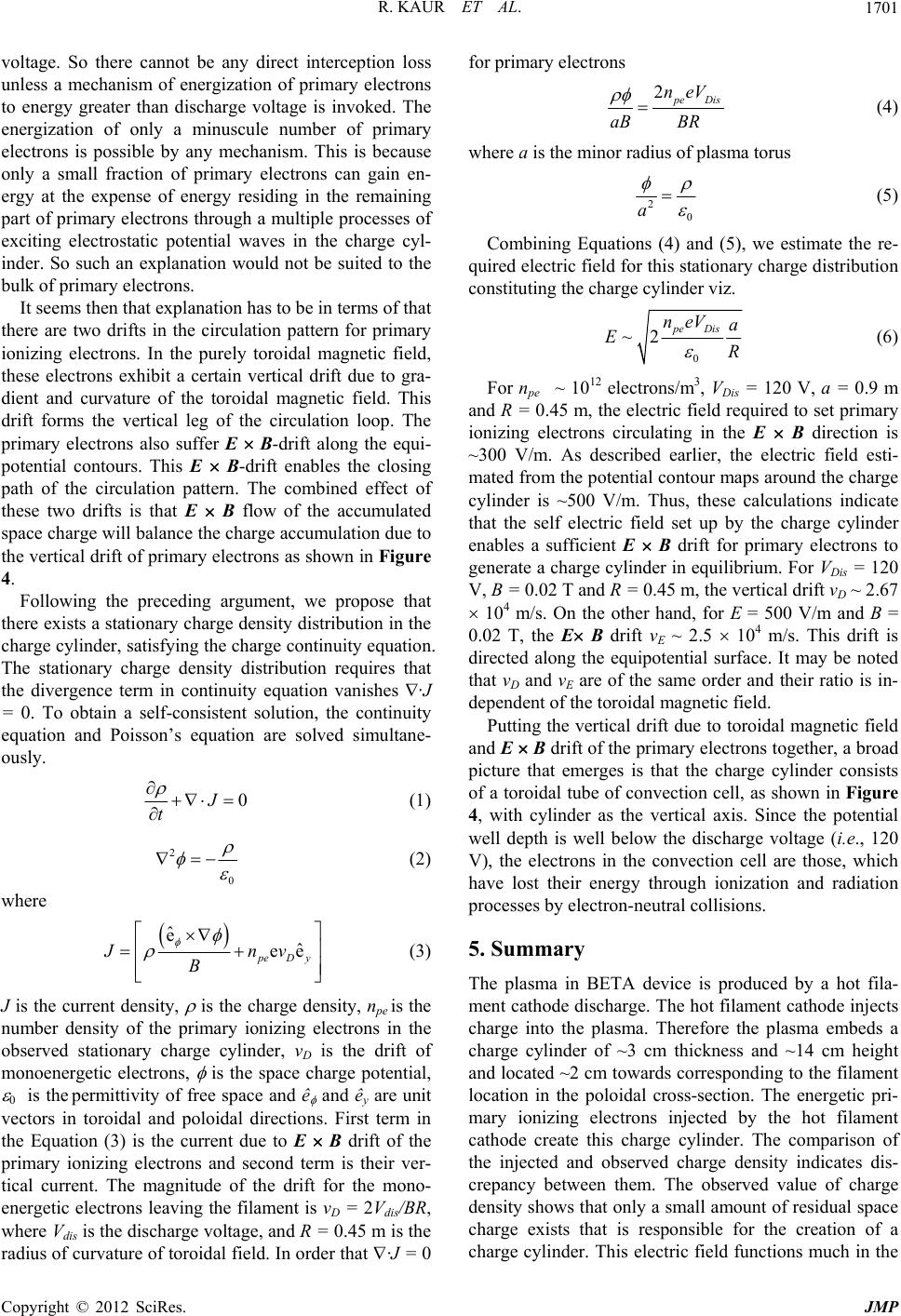 R. KAUR ET AL. 1701 voltage. So there cannot be any direct interception loss unless a mechanism of energization of primary electrons to energy greater than discharge voltage is invoked. The energization of only a minuscule number of primary electrons is possible by any mechanism. This is because only a small fraction of primary electrons can gain en- ergy at the expense of energy residing in the remaining part of primary electrons through a multiple processes of exciting electrostatic potential waves in the charge cyl- inder. So such an explanation would not be suited to the bulk of primary electrons. It seems then that explanation has to be in terms of that there are two drifts in the circulation pattern for primary ionizing electrons. In the purely toroidal magnetic field, these electrons exhibit a certain vertical drift due to gra- dient and curvature of the toroidal magnetic field. This drift forms the vertical leg of the circulation loop. The primary electrons also suffer E B-drift along the equi- potential contours. This E B-drift enables the closing path of the circulation pattern. The combined effect of these two drifts is that E B flow of the accumulated space charge will balance the charge accumulation due to the vertical drift of primary electrons as shown in Figure 4. Following the preceding argument, we propose that there exists a stationary charge density distribution in the charge cylinder, satisfying the charge continuity equation. The stationary charge density distribution requires that the divergence term in continuity equation vanishes ·J = 0. To obtain a self-consistent solution, the continuity equation and Poisson’s equation are solved simultane- ously. 0J t (1) 2 0 (2) where ˆ eˆ ee p eDy nv J B (3) J is the current density, is the charge density, npe is the number density of the primary ionizing electrons in the observed stationary charge cylinder, vD is the drift of monoenergetic electrons, is the space charge potential, 0 is the permittivity of free space and ê and êy are unit vectors in toroidal and poloidal directions. First term in the Equation (3) is the current due to E B drift of the primary ionizing electrons and second term is their ver- tical current. The magnitude of the drift for the mono- energetic electrons leaving the filament is vD = 2Vdis/BR, where Vdis is the discharge voltage, and R = 0.45 m is the radius of curvature of toroidal field. In order that ·J = 0 for primary electrons 2 p eDis neV aB BR (4) where a is the minor radius of plasma torus (5) 2 0 a Combining Equations (4) and (5), we estimate the re- quired electric field for this stationary charge distribution constituting the charge cylinder viz. 0 ~2 pe Dis neV a ER (6) For npe ~ 1012 electrons/m3, VDis = 120 V, a = 0.9 m and R = 0.45 m, the electric field required to set primary ionizing electrons circulating in the E B direction is ~300 V/m. As described earlier, the electric field esti- mated from the potential contour maps around the charge cylinder is ~500 V/m. Thus, these calculations indicate that the self electric field set up by the charge cylinder enables a sufficient E B drift for primary electrons to generate a charge cylinder in equilibrium. For VDis = 120 V, B = 0.02 T and R = 0.45 m, the vertical drift vD ~ 2.67 104 m/s. On the other hand, for E = 500 V/m and B = 0.02 T, the E B drift vE ~ 2.5 104 m/s. This drift is directed along the equipotential surface. It may be noted that vD and vE are of the same order and their ratio is in- dependent of the toroidal magnetic field. Putting the vertical drift due to toroidal magnetic field and E B drift of the primary electrons together, a broad picture that emerges is that the charge cylinder consists of a toroidal tube of convection cell, as shown in Figure 4, with cylinder as the vertical axis. Since the potential well depth is well below the discharge voltage (i.e., 120 V), the electrons in the convection cell are those, which have lost their energy through ionization and radiation processes by electron-neutral collisions. 5. Summary The plasma in BETA device is produced by a hot fila- ment cathode discharge. The hot filament cathode injects charge into the plasma. Therefore the plasma embeds a charge cylinder of ~3 cm thickness and ~14 cm height and located ~2 cm towards corresponding to the filament location in the poloidal cross-section. The energetic pri- mary ionizing electrons injected by the hot filament cathode create this charge cylinder. The comparison of the injected and observed charge density indicates dis- crepancy between them. The observed value of charge density shows that only a small amount of residual space charge exists that is responsible for the creation of a charge cylinder. This electric field functions much in the Copyright © 2012 SciRes. JMP 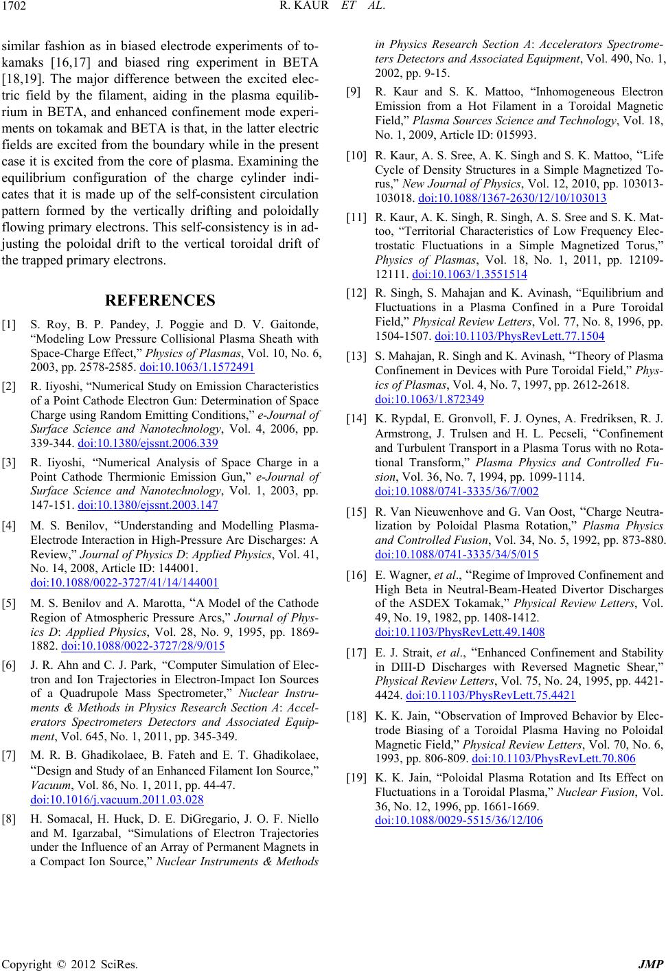 R. KAUR ET AL. Copyright © 2012 SciRes. JMP 1702 similar fashion as in biased electrode experiments of to- kamaks [16,17] and biased ring experiment in BETA [18,19]. The major difference between the excited elec- tric field by the filament, aiding in the plasma equilib- rium in BETA, and enhanced confinement mode experi- ments on tokamak and BETA is that, in the latter electric fields are excited from the boundary while in the present case it is excited from the core of plasma. Examining the equilibrium configuration of the charge cylinder indi- cates that it is made up of the self-consistent circulation pattern formed by the vertically drifting and poloidally flowing primary electrons. This self-consistency is in ad- justing the poloidal drift to the vertical toroidal drift of the trapped primary electrons. REFERENCES [1] S. Roy, B. P. Pandey, J. Poggie and D. V. Gaitonde, “Modeling Low Pressure Collisional Plasma Sheath with Space-Charge Effect,” Physics of Plasmas, Vol. 10, No. 6, 2003, pp. 2578-2585. doi:10.1063/1.1572491 [2] R. Iiyoshi, “Numerical Study on Emission Characteristics of a Point Cathode Electron Gun: Determination of Space Charge using Random Emitting Conditions,” e-Journal of Surface Science and Nanotechnology, Vol. 4, 2006, pp. 339-344. doi:10.1380/ejssnt.2006.339 [3] R. Iiyoshi, “Numerical Analysis of Space Charge in a Point Cathode Thermionic Emission Gun,” e-Journal of Surface Science and Nanotechnology, Vol. 1, 2003, pp. 147-151. doi:10.1380/ejssnt.2003.147 [4] M. S. Benilov, “Understanding and Modelling Plasma- Electrode Interaction in High-Pressure Arc Discharges: A Review,” Journal of Physics D: Applied Physics, Vol. 41, No. 14, 2008, Article ID: 144001. doi:10.1088/0022-3727/41/14/144001 [5] M. S. Benilov and A. Marotta, “A Model of the Cathode Region of Atmospheric Pressure Arcs,” Journal of Phys- ics D: Applied Physics, Vol. 28, No. 9, 1995, pp. 1869- 1882. doi:10.1088/0022-3727/28/9/015 [6] J. R. Ahn and C. J. Park, “Computer Simulation of Elec- tron and Ion Trajectories in Electron-Impact Ion Sources of a Quadrupole Mass Spectrometer,” Nuclear Instru- ments & Methods in Physics Research Section A: Accel- erators Spectrometers Detectors and Associated Equip- ment, Vol. 645, No. 1, 2011, pp. 345-349. [7] M. R. B. Ghadikolaee, B. Fateh and E. T. Ghadikolaee, “Design and Study of an Enhanced Filament Ion Source,” Vacuum, Vol. 86, No. 1, 2011, pp. 44-47. doi:10.1016/j.vacuum.2011.03.028 [8] H. Somacal, H. Huck, D. E. DiGregario, J. O. F. Niello and M. Igarzabal, “Simulations of Electron Trajectories under the Influence of an Array of Permanent Magnets in a Compact Ion Source,” Nuclear Instruments & Methods in Physics Research Section A: Accelerators Spectrome- ters Detectors and Associated Equipment, Vol. 490, No. 1, 2002, pp. 9-15. [9] R. Kaur and S. K. Mattoo, “Inhomogeneous Electron Emission from a Hot Filament in a Toroidal Magnetic Field,” Plasma Sources Science and Technology, Vol. 18, No. 1, 2009, Article ID: 015993. [10] R. Kaur, A. S. Sree, A. K. Singh and S. K. Mattoo, “Life Cycle of Density Structures in a Simple Magnetized To- rus,” New Journal of Physics, Vol. 12, 2010, pp. 103013- 103018. doi:10.1088/1367-2630/12/10/103013 [11] R. Kaur, A. K. Singh, R. Singh, A. S. Sree and S. K. Mat- too, “Territorial Characteristics of Low Frequency Elec- trostatic Fluctuations in a Simple Magnetized Torus,” Physics of Plasmas, Vol. 18, No. 1, 2011, pp. 12109- 12111. doi:10.1063/1.3551514 [12] R. Singh, S. Mahajan and K. Avinash, “Equilibrium and Fluctuations in a Plasma Confined in a Pure Toroidal Field,” Physical Review Letters, Vol. 77, No. 8, 1996, pp. 1504-1507. doi:10.1103/PhysRevLett.77.1504 [13] S. Mahajan, R. Singh and K. Avinash, “Theory of Plasma Confinement in Devices with Pure Toroidal Field,” Phys- ics of Plasmas, Vol. 4, No. 7, 1997, pp. 2612-2618. doi:10.1063/1.872349 [14] K. Rypdal, E. Gronvoll, F. J. Oynes, A. Fredriksen, R. J. Armstrong, J. Trulsen and H. L. Pecseli, “Confinement and Turbulent Transport in a Plasma Torus with no Rota- tional Transform,” Plasma Physics and Controlled Fu- sion, Vol. 36, No. 7, 1994, pp. 1099-1114. doi:10.1088/0741-3335/36/7/002 [15] R. Van Nieuwenhove and G. Van Oost, “Charge Neutra- lization by Poloidal Plasma Rotation,” Plasma Physics and Controlled Fusion, Vol. 34, No. 5, 1992, pp. 873-880. doi:10.1088/0741-3335/34/5/015 [16] E. Wagner, et al., “Regime of Improved Confinement and High Beta in Neutral-Beam-Heated Divertor Discharges of the ASDEX Tokamak,” Physical Review Letters, Vol. 49, No. 19, 1982, pp. 1408-1412. doi:10.1103/PhysRevLett.49.1408 [17] E. J. Strait, et al., “Enhanced Confinement and Stability in DIII-D Discharges with Reversed Magnetic Shear,” Physical Review Letters, Vol. 75, No. 24, 1995, pp. 4421- 4424. doi:10.1103/PhysRevLett.75.4421 [18] K. K. Jain, “Observation of Improved Behavior by Elec- trode Biasing of a Toroidal Plasma Having no Poloidal Magnetic Field,” Physical Review Letters, Vol. 70, No. 6, 1993, pp. 806-809. doi:10.1103/PhysRevLett.70.806 [19] K. K. Jain, “Poloidal Plasma Rotation and Its Effect on Fluctuations in a Toroidal Plasma,” Nuclear Fusion, Vol. 36, No. 12, 1996, pp. 1661-1669. doi:10.1088/0029-5515/36/12/I06 |