

Paper Menu >>
Journal Menu >>
 Journal of Modern Physics, 2012, 3, 1586-1591 http://dx.doi.org/10.4236/jmp.2012.310195 Published Online October 2012 (http://www.SciRP.org/journal/jmp) Guided Wave Studies of Reflective MTN Liquid Crystal Cell Zhidong Zhang, Libin Si, Wenjiang Ye, Xuan Zhou, Li Jiang Department of Applied Physics, Hebei University of Technology, Tianjin, China Email: [email protected] Received August 18, 2012; revised September 16, 2012; accepted September 22, 2012 ABSTRACT The fully-leaky guided wave technique has been used to study the reflective 90˚ MTN liquid crystal cell used for LCOS. The cell is comprised of upper substrate with indium-tin-oxide coating and lower substrate with aluminum coating. Re- flective angle-dependent signals (Rss, Rpp, Rsp and Rps) were recorded over a range of angles of incidence with the cell under application of 0 - 7 Vrms ac electric fields. From the recorded experimental data, we found the reflective signals are quite strong, especially the polarization conversion signals. Fitting the data in reflection with the results of the mod- eling-program gives the information about the pre-tilt and twist of the director as well as the parameters of different optical layers. We found that the pre-tilt angle on the upper substrate is different from that on the bottom in the best fits, which suggests that the indium-tin-oxide and the aluminum coatings have different effects on the alignment layers. Keywords: Fully-Leaky Guided Wave; Liquid Crystal; MTN Cell; Multilayer Optical Theory 1. Introduction Reflective-mode liquid crystal displays have some ad- vantages over transmissive-mode ones such as low power consumption, outdoors readability, thin profile. In 1996, Shin-Tson Wu et al. presented a new reflective-mode display called mixed-mode twisted nematic (MTN) liq- uid crystal cell [1]. It has favorable features like high brightness and contrast ratio, fast response time etc., so it is used for both direct-view displays and reflective-mode projections. The structure and fabrication processes of the MTN cell are nearly identical to a conventional TN cell, but they have two differences: one is that the MTN cell has a smaller retardation (~0.25 μm), the other is that the front director of the MTN cell must be aligned at an angle of β to the polarized direction of the incident light. In general, the geometric structure of the reflective 90˚ MTNcell used for liquid crystal on silicon (LCOS) is shown in Figure 1 [2,3]. On the study of liquid crystal displays, it is vitally im- portant to know the director distribution of a given cell geometry both with and without applied electric fields. In recent decades, a series of guided wave techniques have been developed to explore the director structure in vari- ous cells [4-18]. These techniques mainly utilize that a discrete set of guided modes will be excitated in the liq- uid crystal layer, and the guided modes depend on the distribution of the director. The newly improved fully leaky guided wave technique has also been developed to explore the director distribution of standard liquid crystal cell [8-18]. A two-pyramid coupling method with match- ing fluid is used to couple light into and out of the liquid crystal cell comprised of two standard glass substrates with transparent indium-tin-oxide (ITO) coatings and alignment layers, shown in Figur e 2 [19,20]. Use of low-index pyramids increases the angle range of the incident light allowing the excitation of a number of fully leaky guided modes. Because the light is directly coupled out of the cell, weakly guided-modes are sup- ported over a continuous range of incident, and the varia- tion of optical intensity with angle of incident shows very broad optical features. The light is now leaky from the lower substrate, so the reflective signals are quite weak, especially the polarization conversion signals. However, these signals are particularly sensitive to the twist and tilt of the director, meanwhile, if these signals are too weak, they will be easily interfered by the noise. Now the cell used in our study has a lower substrate with aluminum coating rather than ITO. The aluminum is a good reflector, so the light will be reflected strongly, and it also has the function of electrode. Because the cell is a reflective-mode one, there are only four reflective signals (Rss, Rpp, Rsp, Rps, the first subscript refers to the input polarization, the second to the output) in the ex- periment. By fitting the recorded reflective data to the model data produced by the modeling-program based on both the continuum theory of liquid crystals and the mul- tilayer optical theory, the director distribution may be C opyright © 2012 SciRes. JMP 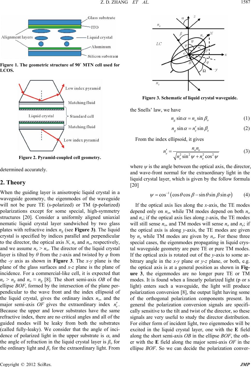 Z. D. ZHANG ET AL. 1587 Figure 1. The geometric structure of 90˚ MTN cell used for LCOS. Figure 2. Pyramid-coupled cell geometry. determined accurately. 2. Theory When the guiding layer is anisotropic liquid crystal in a waveguide geometry, the eigenmodes of the waveguide will not be pure TE (s-polarized) or TM (p-polarized) polarizations except for some special, high-symmetry structures [20]. Consider a uniformly aligned uniaxial nematic liquid crystal layer sandwiched by two glass plates with refractive index ng (see Figure 3). The liquid crystal is specified by indices parallel and perpendicular to the director, the optical axis N, ne and no, respectively, and we assume ne > no. The director of the liquid crystal layer is tilted by θ from the z-axis and twisted by φ from the -y axis as shown in Figure 3. The x-y plane is the plane of the glass surfaces and x-z plane is the plane of incidence. For a commercial-like cell, it is expected that ne > n g and no ≈ n g [8]. The short semi-axis OB of the ellipse BOF, formed by the intersection of the plane per- pendicular to the wave front and the index ellipsoid of the liquid crystal, gives the ordinary index no, and the major semi-axis OF gives the extraordinary index e Figure 3. Schematic of liquid crystal waveguide. the Snells’ law, we have n . Because the upper and lower substrates have the same refractive index, there are no critical angles and all of the guided modes will be leaky from both the substrates (called fully-leaky). We consider that the angle of inci- dence of polarized light in the upper substrate is , and the angle of refraction in the liquid crystal layer is βo for the ordinary light and βe for the extraordinary light. From sin sin g oo nn (1) sin sin g ee nn (2) From the index ellipsoid, it gives 222 2 sin cos oe e oe nn n nn (3) where ψ is the angle between the optical axis, the director, and wave-front normal for the extraordinary light in the liquid crystal layer, which is given by the follow formula [20] 1 coscos cossin sinsin (4) If the optical axis lies along the x-axis, the TE modes depend only on no, while TM modes depend on both no and ne; if the optical axis lies along z-axis, the TE modes will still sense no, and TM modes will sense no and ne; if the optical axis is along y-axis, the TE modes are given by ne while TM modes are given by no. For these three special cases, the eigenmodes propagating in liquid crys- tal waveguide geometry are pure TE or pure TM modes. If the optical axis is rotated out of the y-axis to some ar- bitrary angle in the x-y plane or y-z plane, or both, e.g. the optical axis is at a general position as shown in Fig- ure 3, the eigenmodes are no longer pure TE or TM modes. It is found when a linearly polarized light (p or s light) enters such a waveguide, the light will produce polarization conversion [8], the output light having some of the orthogonal polarization components present. In general the polarization conversion signals are specifi- cally sensitive to the tilt and twist of the director, so these signals are very useful to study the director distribution. For either form of incident light, two eigenmodes will be excited in the liquid crystal layer, one with the E field along the short semi-axis OB in the ellipse BOF, the oth- er with the E field along the major semi-axis OF in the ellipse BOF. So we can decide the polarization conver- Copyright © 2012 SciRes. JMP 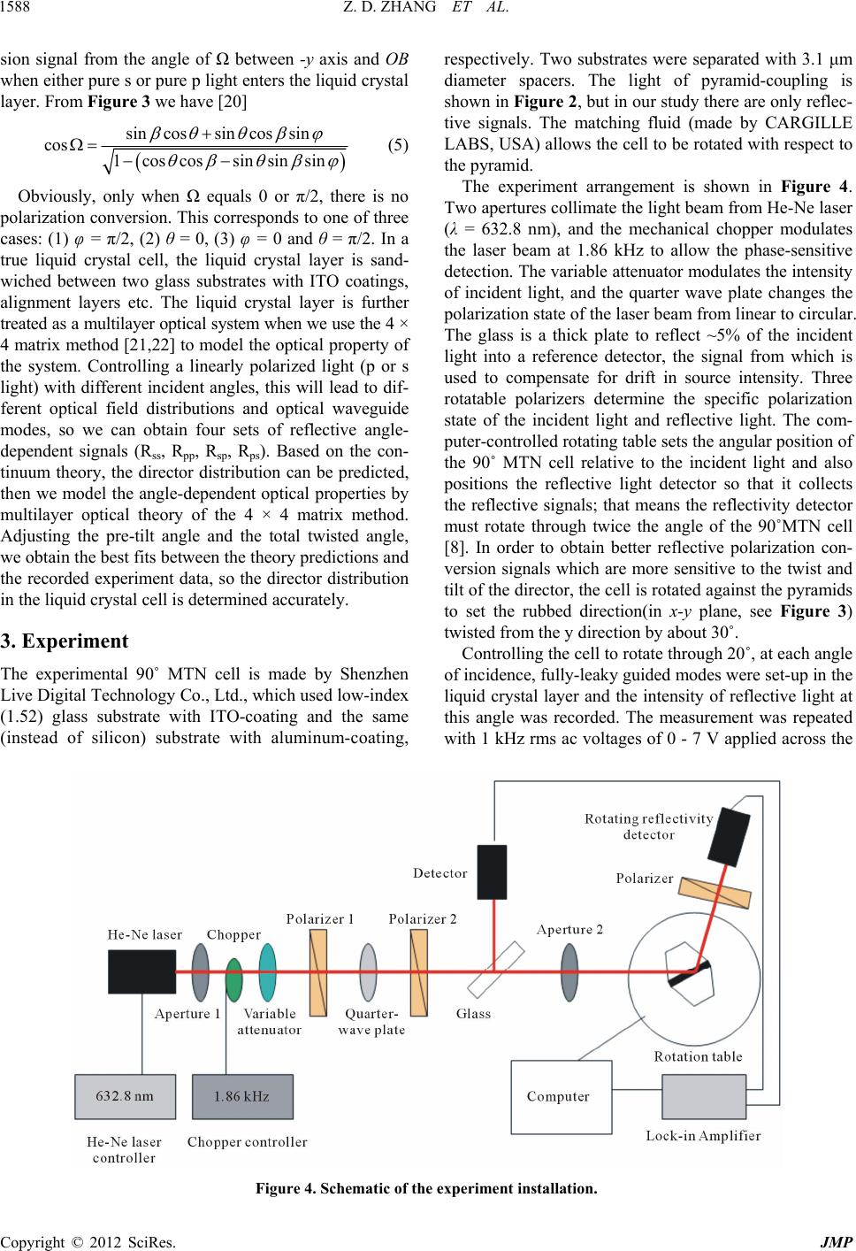 Z. D. ZHANG ET AL. Copyright © 2012 SciRes. JMP 1588 sion signal from the angle of Ω between -y axis and OB when either pure s or pure p light enters the liquid crystal layer. From Figure 3 we have [20] respectively. Two substrates were separated with 3.1 μm diameter spacers. The light of pyramid-coupling is shown in Figure 2, but in our study there are only reflec- tive signals. The matching fluid (made by CARGILLE LABS, USA) allows the cell to be rotated with respect to the pyramid. sincossin c cos 1cos cossin os sin sin sin (5) The experiment arrangement is shown in Figure 4. Two apertures collimate the light beam from He-Ne laser (λ = 632.8 nm), and the mechanical chopper modulates the laser beam at 1.86 kHz to allow the phase-sensitive detection. The variable attenuator modulates the intensity of incident light, and the quarter wave plate changes the polarization state of the laser beam from linear to circular. The glass is a thick plate to reflect ~5% of the incident light into a reference detector, the signal from which is used to compensate for drift in source intensity. Three rotatable polarizers determine the specific polarization state of the incident light and reflective light. The com- puter-controlled rotating table sets the angular position of the 90˚ MTN cell relative to the incident light and also positions the reflective light detector so that it collects the reflective signals; that means the reflectivity detector must rotate through twice the angle of the 90˚MTN cell [8]. In order to obtain better reflective polarization con- version signals which are more sensitive to the twist and tilt of the director, the cell is rotated against the pyramids to set the rubbed direction(in x-y plane, see Figure 3) twisted from the y direction by about 30˚. Obviously, only when Ω equals 0 or π/2, there is no polarization conversion. This corresponds to one of three cases: (1) φ = π/2, (2) θ = 0, (3) φ = 0 and θ = π/2. In a true liquid crystal cell, the liquid crystal layer is sand- wiched between two glass substrates with ITO coatings, alignment layers etc. The liquid crystal layer is further treated as a multilayer optical system when we use the 4 × 4 matrix method [21,22] to model the optical property of the system. Controlling a linearly polarized light (p or s light) with different incident angles, this will lead to dif- ferent optical field distributions and optical waveguide modes, so we can obtain four sets of reflective angle- dependent signals (Rss, Rpp, Rsp, Rps). Based on the con- tinuum theory, the director distribution can be predicted, then we model the angle-dependent optical properties by multilayer optical theory of the 4 × 4 matrix method. Adjusting the pre-tilt angle and the total twisted angle, we obtain the best fits between the theory predictions and the recorded experiment data, so the director distribution in the liquid crystal cell is determined accurately. 3. Experiment Controlling the cell to rotate through 20˚, at each angle of incidence, fully-leaky guided modes were set-up in the liquid crystal layer and the intensity of reflective light at this angle was recorded. The measurement was repeated with 1 kHz rms ac voltages of 0 - 7 V applied across the The experimental 90˚ MTN cell is made by Shenzhen Live Digital Technology Co., Ltd., which used low-index (1.52) glass substrate with ITO-coating and the same (instead of silicon) substrate with aluminum-coating, Figure 4. Schematic of the experiment installation. 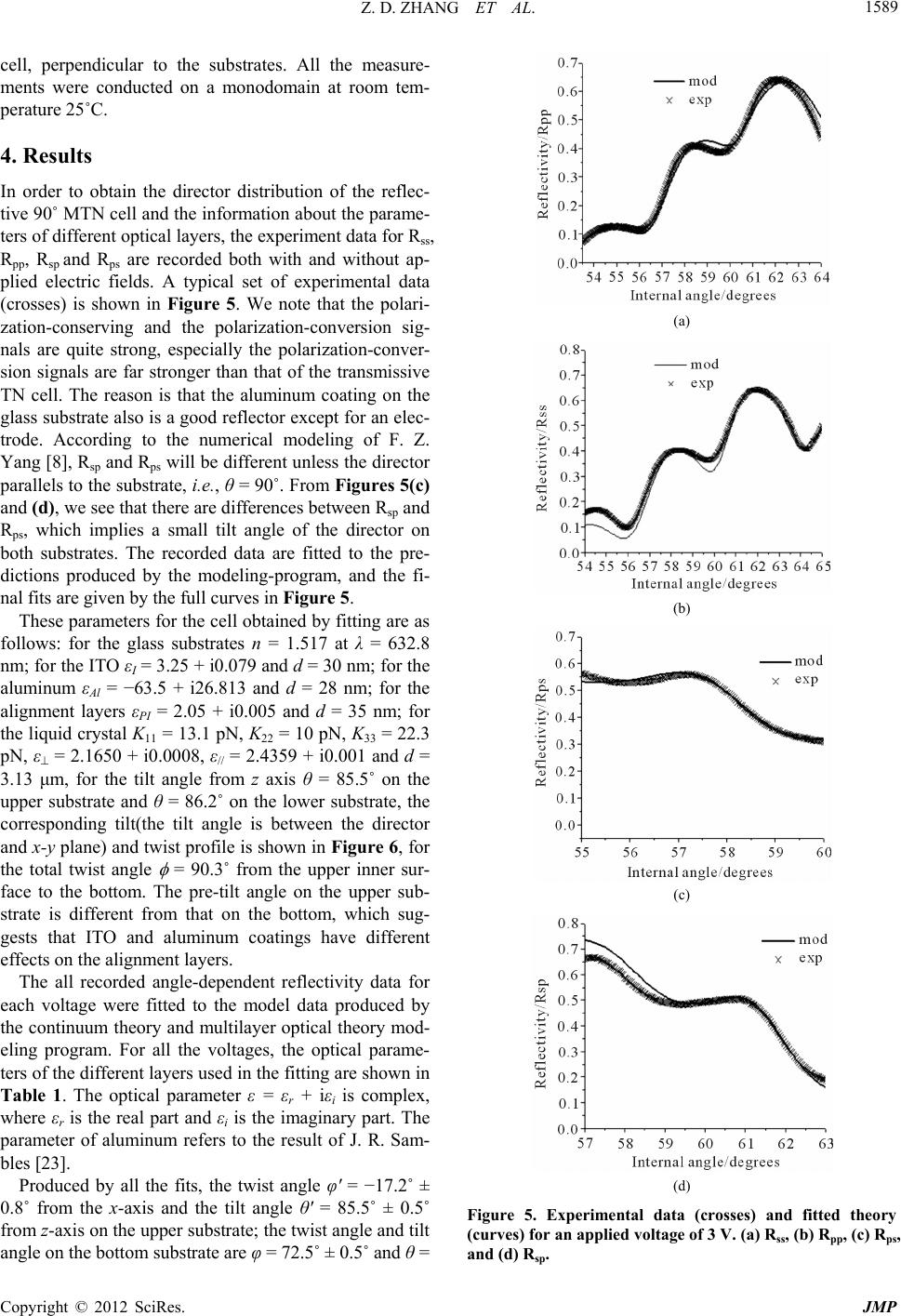 Z. D. ZHANG ET AL. 1589 cell, perpendicular to the substrates. All the measure- ments were conducted on a monodomain at room tem- perature 25˚C. 4. Results In order to obtain the director distribution of the reflec- tive 90˚ MTN cell and the information about the parame- ters of different optical layers, the experiment data for Rss, Rpp, Rsp and Rps are recorded both with and without ap- plied electric fields. A typical set of experimental data (crosses) is shown in Figure 5. We note that the polari- zation-conserving and the polarization-conversion sig- nals are quite strong, especially the polarization-conver- sion signals are far stronger than that of the transmissive TN cell. The reason is that the aluminum coating on the glass substrate also is a good reflector except for an elec- trode. According to the numerical modeling of F. Z. Yang [8], Rsp and Rps will be different unless the director parallels to the substrate, i.e., θ = 90˚. From Figures 5(c) and (d), we see that there are differences between Rsp and Rps, which implies a small tilt angle of the director on both substrates. The recorded data are fitted to the pre- dictions produced by the modeling-program, and the fi- nal fits are given by the full curves in Figure 5. These parameters for the cell obtained by fitting are as follows: for the glass substrates n = 1.517 at λ = 632.8 nm; for the ITO εI = 3.25 + i0.079 and d = 30 nm; for the aluminum εAl = −63.5 + i26.813 and d = 28 nm; for the alignment layers εPI = 2.05 + i0.005 and d = 35 nm; for the liquid crystal K11 = 13.1 pN, K22 = 10 pN, K33 = 22.3 pN, ε = 2.1650 + i0.0008, ε// = 2.4359 + i0.001 and d = 3.13 μm, for the tilt angle from z axis θ = 85.5˚ on the upper substrate and θ = 86.2˚ on the lower substrate, the corresponding tilt(the tilt angle is between the director and x-y plane) and twist profile is shown in Figure 6, for the total twist angle = 90.3˚ from the upper inner sur- face to the bottom. The pre-tilt angle on the upper sub- strate is different from that on the bottom, which sug- gests that ITO and aluminum coatings have different effects on the alignment layers. The all recorded angle-dependent reflectivity data for each voltage were fitted to the model data produced by the continuum theory and multilayer optical theory mod- eling program. For all the voltages, the optical parame- ters of the different layers used in the fitting are shown in Table 1. The optical parameter ε = εr + iεi is complex, where εr is the real part and εi is the imaginary part. The parameter of aluminum refers to the result of J. R. Sam- bles [23]. Produced by all the fits, the twist angle φ' = −17.2˚ ± 0.8˚ from the x-axis and the tilt angle θ' = 85.5˚ ± 0.5˚ from z-axis on the upper substrate; the twist angle and tilt angle on the bottom substrate are φ = 72.5˚ ± 0.5˚ and θ = (a) (b) (c) (d) Figure 5. Experimental data (crosses) and fitted theory (curves) for an applied voltage of 3 V. (a) Rss, (b) Rpp, (c) Rps, and (d) Rsp. Copyright © 2012 SciRes. JMP 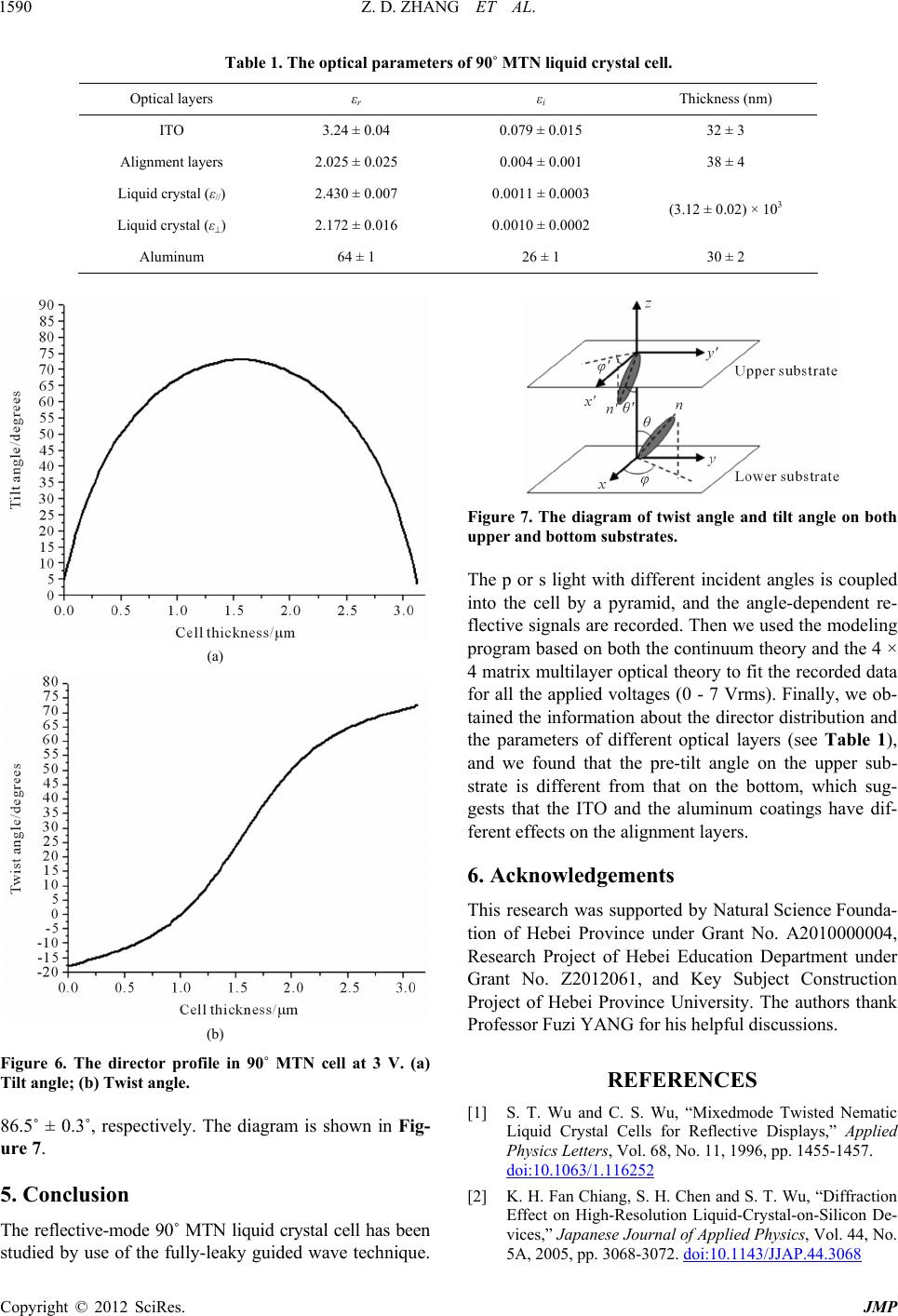 Z. D. ZHANG ET AL. 1590 Table 1. The optical parameters of 90˚ MTN liquid crystal cell. Optical layers εr εi Thickness (nm) ITO 3.24 ± 0.04 0.079 ± 0.015 32 ± 3 Alignment layers 2.025 ± 0.025 0.004 ± 0.001 38 ± 4 Liquid crystal (ε//) 2.430 ± 0.007 0.0011 ± 0.0003 Liquid crystal (ε) 2.172 ± 0.016 0.0010 ± 0.0002 (3.12 ± 0.02) × 103 Aluminum 64 ± 1 26 ± 1 30 ± 2 (a) (b) Figure 6. The director profile in 90˚ MTN cell at 3 V. (a) Tilt angle; (b) Twist angle. 86.5˚ ± 0.3˚, respectively. The diagram is shown in Fig- ure 7. 5. Conclusion The reflective-mode 90˚ MTN liquid crystal cell has been studied by use of the fully-leaky guided wave technique. Figure 7. The diagram of twist angle and tilt angle on both upper and bottom substrates. The p or s light with different incident angles is coupled into the cell by a pyramid, and the angle-dependent re- flective signals are recorded. Then we used the modeling program based on both the continuum theory and the 4 × 4 matrix multilayer optical theory to fit the recorded data for all the applied voltages (0 - 7 Vrms). Finally, we ob- tained the information about the director distribution and the parameters of different optical layers (see Table 1), and we found that the pre-tilt angle on the upper sub- strate is different from that on the bottom, which sug- gests that the ITO and the aluminum coatings have dif- ferent effects on the alignment layers. 6. Acknowledgements This research was supported by Natural Science Founda- tion of Hebei Province under Grant No. A2010000004, Research Project of Hebei Education Department under Grant No. Z2012061, and Key Subject Construction Project of Hebei Province University. The authors thank Professor Fuzi YANG for his helpful discussions. REFERENCES [1] S. T. Wu and C. S. Wu, “Mixedmode Twisted Nematic Liquid Crystal Cells for Reflective Displays,” Applied Physics Letters, Vol. 68, No. 11, 1996, pp. 1455-1457. doi:10.1063/1.116252 [2] K. H. Fan Chiang, S. H. Chen and S. T. Wu, “Diffraction Effect on High-Resolution Liquid-Crystal-on-Silicon De- vices,” Japanese Journal of Applied Physics, Vol. 44, No. 5A, 2005, pp. 3068-3072. doi:10.1143/JJAP.44.3068 Copyright © 2012 SciRes. JMP  Z. D. ZHANG ET AL. 1591 [3] J. Chen, S. M. Morris, T. D. Wilkinson, J. P. Freeman, and H. J. Coles, “High Speed Liquid Crystal over Silicon Display Based on the Flexoelectro-Optic Effect,” Optics Express, Vol. 17, No. 9, 2009, pp. 7130-7137. doi:10.1364/OE.17.007130 [4] F. Z. Yang, L. Z. Ruan, and J. R. Sambles, “Polarization- Conversion Guided Mode (PCGM) Technique for Ex- ploring Thin Anisotropic Surface Layers,” Optics Express, Vol. 15, No. 18, 2007, pp. 11234-11240. doi:10.1364/OE.15.011234 [5] F. Z. Yang, L. Z. Ruan and J. R. Sambles, “Exploration of the Surface Director Profile in a Liquid Crystal Cell Us- ing Coupling Between the Surface Plasmon and Half- Leaky Optical Guided Modes,” Applied Physics Letters, Vol. 92, No. 15, 2008, pp. 1-3. doi:10.1063/1.2908224 [6] F. Z. Yang, L. Z. Ruan, S. A. Jewell and J. R. Sambles, “Coupled Surface Plasmons and Optical Guided Wave Exploration of Near-Surface Director Profile,” New Jour- nal of Physics, Vol. 9, No. 49, 2007, pp. 1-11. [7] F. Z. Yang, S. A. Jewell, L. Z. Ruan and J. R. Sambles, “ Complex Permittivities of a Nematic Liquid Crystal in a Hybrid-Aligned Cell,” Journal of the Optic Society of America B, Vol. 24, No. 3, 2007, pp. 527-531. doi:10.1364/JOSAB.24.000527 [8] F. Z. Yang and J. R. Sambles, “Optical Fully Leaky Mode Characterization of Standard Liquid-Crystal Cell,” Jour- nal of the Optic Society of America B, Vol. 16, No. 3, 1999, pp. 488-497. doi:10.1364/JOSAB.16.000488 [9] F. Z. Yang, H. J. Gao and J. R. Sambles, “Fully Leaky Guided Wave Determination of the Original Alignment Direction for the Directors at the Walls in a Twisted Ne- matic Liquid Crystal Cell,” Journal of Applied Physics, Vol. 92, No. 4, 2002, pp. 1744-1751. doi:10.1063/1.1491025 [10] B. Hodder, F. Yang and J. R. Sambles, “Optical Charac- terization of the Director Profile in a Ferroelectric Liquid Crystal Cell with Homeotropic Alignment,” Journal of Applied Physics, Vol. 89, No. 1, 2001, pp. 5-9. doi:10.1063/1.1330549 [11] F. Z. Yang, J. R. Sambles, Y. M. Dong and H. J. Gao, “Fully Leaky Guided Wave Determination of the Polar Anchoring Energy of a Homogeneously Aligned Nematic Liquid Crystal,” Journal of Applied Physics, Vol. 87, No. 6, 2000, pp. 2726-2735. doi:10.1063/1.372247 [12] S. A. Jewell and J. R. Sambles, “Fully Leaky Guided Mode Study of the Flexoelectric Effect and Surface Po- larization in Hybrid Aligned Nematic Cells,” Journal of Applied Physics, Vol. 92, No. 1, 2002, pp. 19-24. doi:10.1063/1.1483392 [13] L. Z. Ruan, F. Z. Yang and J. R. Sambles, “Voltage De- pendent Director of a Homeotropic Negative Liquid Crystal Cell,” Applied Physics Letters, Vol. 93, No. 3, 2008, Article ID: 031909. [14] S. A. Jewell and J. R. Sambles, “Fully-Leaky Guided Mode Measurement of the Flexoelectric Constant (e11+ e33) of a Nematic Liquid Crystal,” Crystals and Liquid Crystals, Vol. 401, No. 1, 2003, pp. 67-73. doi:10.1080/744815187 [15] S. L. Cornford, T. S. Taphouse, C. J. P. Newton and J. R. Sambles, “Determination of the Director Profile in a Ne- matic Cell from Guided Wave Data: An Inverse Prob- lem,” New Journal of Physics, Vol. 9, No. 166, 2007, pp. 1-15. [16] S. A. Jewell and J. R. Sambles, “Optical Characterization of a Dual-Frequency Hybrid Aligned Nematic Liquid Crystal Cell,” Optics Express, Vol. 13, No. 7, 2005, pp. 2627-2633. doi:10.1364/OPEX.13.002627 [17] H. Y. Xing , W. J. Ye , N. F. Wu , Z. D. Zhang and L. Xuan, “Exploration of the Sum of Flexoelectric Coef- fcients of Nematic Liquid Crystals,” Chinese Optics Let- ters, Vol. 10, No. 5, 2012, Article ID: 052301. [18] H. Y. Xing, W. J. Ye, N. F. Wu, L. B. Si and Z. D. Zhang, “Determination of Director Profile in the Vertical Align- ment Nematic Liquid Crystal Cell by the Full Leaky Guided Mode Technique,” Solid State Phenomena, Vol. 181-182, 2012, pp. 265-268. doi:10.4028/www.scientific.net/SSP.181-182.265 [19] F. Z. Yang, J. R. Samble and G. W. Bradberry, “Guided Modes and Related Optical Techniques Liquid Crystal Alignment Studies,” In: S. J. Elston and J. R. Sambles, Eds., The Optics Thermotropic Liquid Crystals, Taloy and Francis Ltd., London, 1998, pp. 85-95. [20] F. Z. Yang and J. R. Samble, “Guided Mode Studies of Liquid Crystal Layers,” In: M. Iwamoto, K. Kaneto and S. Mashiko, Eds., Nanotechnology and Nano-Interface Con- trolled Electronic Devices, Taylor and Francis Ltd., Lon- don, 2003, pp. 271-280. doi:10.1016/B978-044451091-4/50016-9 [21] D. W. Berreman, “Optics in Stratified and Anisotropic Media: 4 × 4 Matrix Formulation,” Journal of the Optic Society of America A, Vol. 62, No. 4, 1972, pp. 502-510. doi:10.1364/JOSA.62.000502 [22] D. Y. K. Ko and J. R. Sambles, “Scattering Matrix Me- thod for Propagation of Radiation in Stratified Media: Attenuated Total Reflection Studies of Liquid Crystals,” Journal of the Optic Society of America A, Vol. 5, No. 11, 1988, pp. 1863-1866. doi:10.1364/JOSAA.5.001863 [23] J. R. Sambles, G. W. Bradbery and F. Z. Yang, “Optical Excitation of Surface Plasmons: An Introduction,” Con- temporary Physics, Vol. 32, No. 3, 1991, pp. 173-183. doi:10.1080/00107519108211048 Copyright © 2012 SciRes. JMP |