

Paper Menu >>
Journal Menu >>
 Journal of Modern Physics, 2012, 3, 1494-1502 http://dx.doi.org/10.4236/jmp.2012.310185 Published Online October 2012 (http://www.SciRP.org/journal/jmp) Probe and Emission Spectrometry Diagnostics in Hollow Cathode Magnetron N. P. Poluektov, Yu. P. Tsar’gorodsev, I. I. Usatov, A. G. Evstigneev, I. A. Kamyschov Department of Physics, Faculty of Electronics, Moscow State Forest University, Mytischi, Russia Email: [email protected] Received August 10, 2012; revised September 12, 2012; accepted September 19, 2012 ABSTRACT This paper deals with the characterization of an ionized physical vapor deposition (IPVD) by means of hollow cathode magnetron. Langmuir probe, optical emission spectroscopy measurements were used to study a mechanism for the pro- duction of excited argon and copper atoms and ions. The kinetic processes of excitation were considered and the main processes were determined using results of measurements. The pressure range is 0.5 - 10 mTorr with 1- 5 kW discharge power. Plasma parameters such as electron densities and temperatures, electron energy distribution function, plasma space and floating potentials as a function of the position, pressure and power in the growth chamber were measured. The plasma density is up to 1012 cm−3 at 20 cm from the magnetron for 10 mTorr. Keywords: Hollow Cathode Magnetron; Ionized Physical Vapor Deposition 1. Introduction The hollow cathode magnetron (HCM) is new type of a source of plasma for films deposition using of atoms and ions of metal. Feature of this discharge is high density plasma (more than 1012 cm−3 at pressure a few millitorrs) created in big (103 cm3) volume, low (10 - 50 eV) and easily changeable energy of the ions arriving at the sub- strate. The characteristic difference between this tech- nique and conventional approaches is that high fraction of the sputtered material is ionized, while in traditional magnetron sputtering, the sputtered species are almost exclusively neutral. The ionized physical vapor deposi- tion (IPVD) method is increasingly used to deposit diffu- sion barriers and copper seed layers materials into high- aspect ratio vias and trenches for microelectronics fabri- cation [1-5]. Ionized metal plasmas have been also used to produce nanosize interlayers and graded structures by intermixing of condensing ions and substrate. Metal plasmas are often used in deposition of nanosized com- pound multilayers that can undergo phase changes at elevated temperatures [6,7]. Film deposition in this dis- charge is accompanied by the streams of low-energy ions that allow to receive a film with unique properties. Several techniques have been developed for obtaining an ionized growth flux; the plasma may be generated, for example, by electron cyclotron resonance [8] or by in- ductively coupled radio-frequency (rf) power [3-7]. HCM uses a single dc power supply to both sputter and ionize the target material unlike other IPVD tools which use secondary inductively coupled or ECR plasma sources for ionization of sputtered atoms. The quality of the deposited films depends on the quantity and energy of the particle flux and substrate temperature. In the HCM these values differ greatly from those in the con- vectional magnetron. In a conventional magnetron main contribution to the heat flux on the substrate is made by atoms of the target and buffer gas. In HCM main contri- bution is produced by ions of the buffer gas and metal. Such ion assistance allows the deposition of high quality films on complex shaped substrates. Only a few papers have been published which deal with investigation HCM [1,2,9,10]. The purpose of this paper is to study a mecha- nism for the production of excited argon and copper at- oms and ions. For this the spatial distribution of plasma parameters in hollow cathode magnetron was studied using probe and optical emission spectroscopy tech- niques. 2. Experimental Apparatus Figure 1 presents our experimental set-up. The cathode consists of a cup-shaped Cu target (8 cm i.d. and 7 cm long) from which plasma diffuses into a reactor (35 cm diameter, 55 cm length). The chamber was pumped to base pressure 5 × 10⁻⁶ Torr using a turbomolecular pump. C opyright © 2012 SciRes. JMP 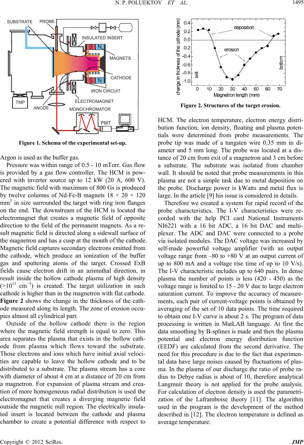 N. P. POLUEKTOV ET AL. 1495 MONOCHROMATOR PROBE CATHODE MAGNETS INSULATED INSERT TMP ANODE SUBSTRATE ELECTROMAGNET N N S S IRON CIRCUIT PMT Figure 1. Schema of the experimental set-up. Argon is used as the buffer gas. Pressure was within range of 0.5 - 10 mTorr. Gas flow is provided by a gas flow controller. The HCM is pow- ered with inverter source up to 12 kW (20 A, 600 V). The magnetic field with maximum of 800 Gs is produced by twelve columns of Nd-Fe-B magnets 18 × 20 × 120 mm3 in size surrounded the target with ring iron flanges on the end. The downstream of the HCM is located the electromagnet that creates a magnetic field of opposite direction to the field of the permanent magnets. As a re- sult magnetic field is directed along a sidewall surface of the magnetron and has a cusp at the mouth of the cathode. Magnetic field captures secondary electrons emitted from the cathode, which produce an ionization of the buffer gas and sputtering atoms of the target. Crossed ExB fields cause electron drift in an azimuthal direction, in result inside the hollow cathode plasma of high density (>1013 cm−3) is created. The target utilization in such cathode is higher than in the magnetron with flat cathode. Figure 2 shows the change in the thickness of the cath- ode measured along its length. The zone of erosion occu- pies almost all cylindrical part. Outside of the hollow cathode there is the region where the magnetic field strength is equal to zero. This area separates the plasma that exists in the hollow cath- ode from plasma which flows toward the substrate. Those electrons and ions which have initial axial veloci- ties are capable to leave the hollow cathode and to be distributed to a substrate. The plasma stream has a core with diameter of about 4 cm at a distance of 20 cm from a magnetron. For expansion of plasma stream and crea- tion of more homogeneous radial distribution is used the electromagnet that creates a diverging magnetic field outside the magnetic null region. The electrically insula- ted insert is located between the cathode and plasma chamber to create a potential difference with respect to Figure 2. Structures of the target erosion. HCM. The electron temperature, electron energy distri- bution function, ion density, floating and plasma poten- tials were determined from probe measurements. The probe tip was made of a tungsten wire 0.35 mm in di- ameter and 5 mm long. The probe was located at a dis- tance of 20 cm from exit of a magnetron and 3 cm before a substrate. The substrate was isolated from chamber wall. It should be noted that probe measurements in this plasma are not a simple task due to metal deposition on the probe. Discharge power is kWatts and metal flux is large. In the article [9] his issue is considered in details. Therefore we created a system for rapid record of the probe characteristics. The I-V characteristics were re- corded with the help PCI card National Instruments NI6221 with a 16 bit ADC, a 16 bit DAC and multi- plexer. The ADC and DAC were connected to a probe via isolated modules. The DAC voltage was increased by self-made powerful voltage amplifier (with an output voltage range from –80 to +80 V at an output current of up to 800 mA and a voltage rise time of up to 10 V/s). The I-V characteristic includes up to 640 pairs. In dense plasma the number of points is less (420 - 450) as the voltage range is limited to 15 - 20 V due to large electron saturation current. To improve the accuracy of measure- ments, each pair of current-voltage points is obtained by averaging of the set of 10 data points. The time required to obtain one I-V curve is about 2 s. The program of data processing is written in MatLAB language. At first the data smoothing by B-splines is made and then the plasma potential and electron energy distribution function (EEDF) are calculated from the second derivative. The need for this procedure is due to the fact that experimen- tal data have large noises caused by fluctuations of plas- ma. In the plasma of our discharge the ratio of probe ra- dius to Debye radius is about of 10, therefore analytical Langmuir theory is not applied for the probe analysis. For calculation of electron density is used the parametri- zation of the Laframboise theory [11]. The algorithm used in the program is the development of the method described in [12]. The electron temperature is defined as average temperature: Copyright © 2012 SciRes. JMP 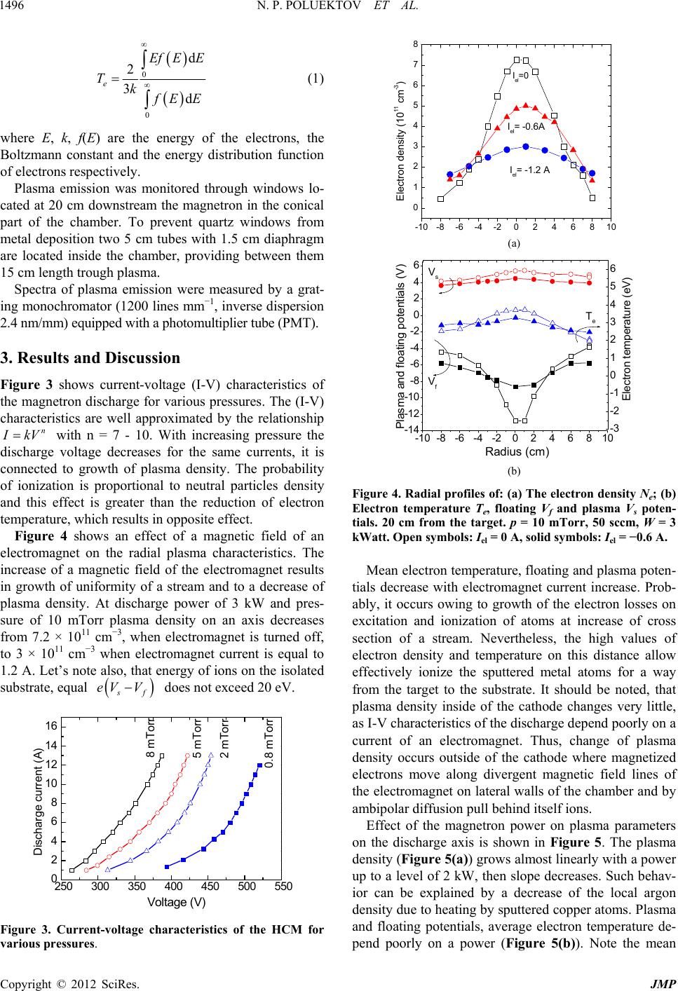 N. P. POLUEKTOV ET AL. 1496 0 0 d 2 3d e Ef EE Tk f EE (1) where E, k, f(E) are the energy of the electrons, the Boltzmann constant and the energy distribution function of electrons respectively. Plasma emission was monitored through windows lo- cated at 20 cm downstream the magnetron in the conical part of the chamber. To prevent quartz windows from metal deposition two 5 cm tubes with 1.5 cm diaphragm are located inside the chamber, providing between them 15 cm length trough plasma. Spectra of plasma emission were measured by a grat- ing monochromator (1200 lines mm−1, inverse dispersion 2.4 nm/mm) equipped with a photomultiplier tube (PMT). 3. Results and Discussion Figure 3 shows current-voltage (I-V) characteristics of the magnetron discharge for various pressures. The (I-V) characteristics are well approximated by the relationship n I kV with n = 7 - 10. With increasing pressure the discharge voltage decreases for the same currents, it is connected to growth of plasma density. The probability of ionization is proportional to neutral particles density and this effect is greater than the reduction of electron temperature, which results in opposite effect. Figure 4 shows an effect of a magnetic field of an electromagnet on the radial plasma characteristics. The increase of a magnetic field of the electromagnet results in growth of uniformity of a stream and to a decrease of plasma density. At discharge power of 3 kW and pres- sure of 10 mTorr plasma density on an axis decreases from 7.2 × 1011 cm−3, when electromagnet is turned off, to 3 × 1011 cm−3 when electromagnet current is equal to 1.2 A. Let’s note also, that energy of ions on the isolated substrate, equal s f eV V does not exceed 20 eV. 250 300 350 400 450 500 550 0 2 4 6 8 10 12 14 16 0.8 mTorr Discharge current (A) Voltage (V) 2 mTor r 5 mTorr 8 mTorr Figure 3. Current-voltage characteristics of the HCM for various pressures. -10-8-6-4-20246810 0 1 2 3 4 5 6 7 8 a) Electron density (1011 cm-3) Iel= -0.6 A Iel= -1.2 A Iel=0 (a) -10 -8-6-4-20246810 -14 -12 -10 -8 -6 -4 -2 0 2 4 6 -3 -2 -1 0 1 2 3 4 5 6 Plasma and floating potentials (V) Radius (cm) b) Vf Vs Elec tr o n te m p er a t ur e (eV ) Te (b) Figure 4. Radial profiles of: (a) The electron density Ne; (b) Electron temperature Te, floating Vf and plasma Vs poten- tials. 20 cm from the target. p = 10 mTorr, 50 sccm, W = 3 kWatt. Open symbols: Iel = 0 A, solid symbols: Iel = −0.6 A. Mean electron temperature, floating and plasma poten- tials decrease with electromagnet current increase. Prob- ably, it occurs owing to growth of the electron losses on excitation and ionization of atoms at increase of cross section of a stream. Nevertheless, the high values of electron density and temperature on this distance allow effectively ionize the sputtered metal atoms for a way from the target to the substrate. It should be noted, that plasma density inside of the cathode changes very little, as I-V characteristics of the discharge depend poorly on a current of an electromagnet. Thus, change of plasma density occurs outside of the cathode where magnetized electrons move along divergent magnetic field lines of the electromagnet on lateral walls of the chamber and by ambipolar diffusion pull behind itself ions. Effect of the magnetron power on plasma parameters on the discharge axis is shown in Figure 5. The plasma density (Figure 5(a)) grows almost linearly with a power up to a level of 2 kW, then slope decreases. Such behav- ior can be explained by a decrease of the local argon density due to heating by sputtered copper atoms. Plasma and floating potentials, average electron temperature de- pend poorly on a power (Figure 5(b)). Note the mean Copyright © 2012 SciRes. JMP 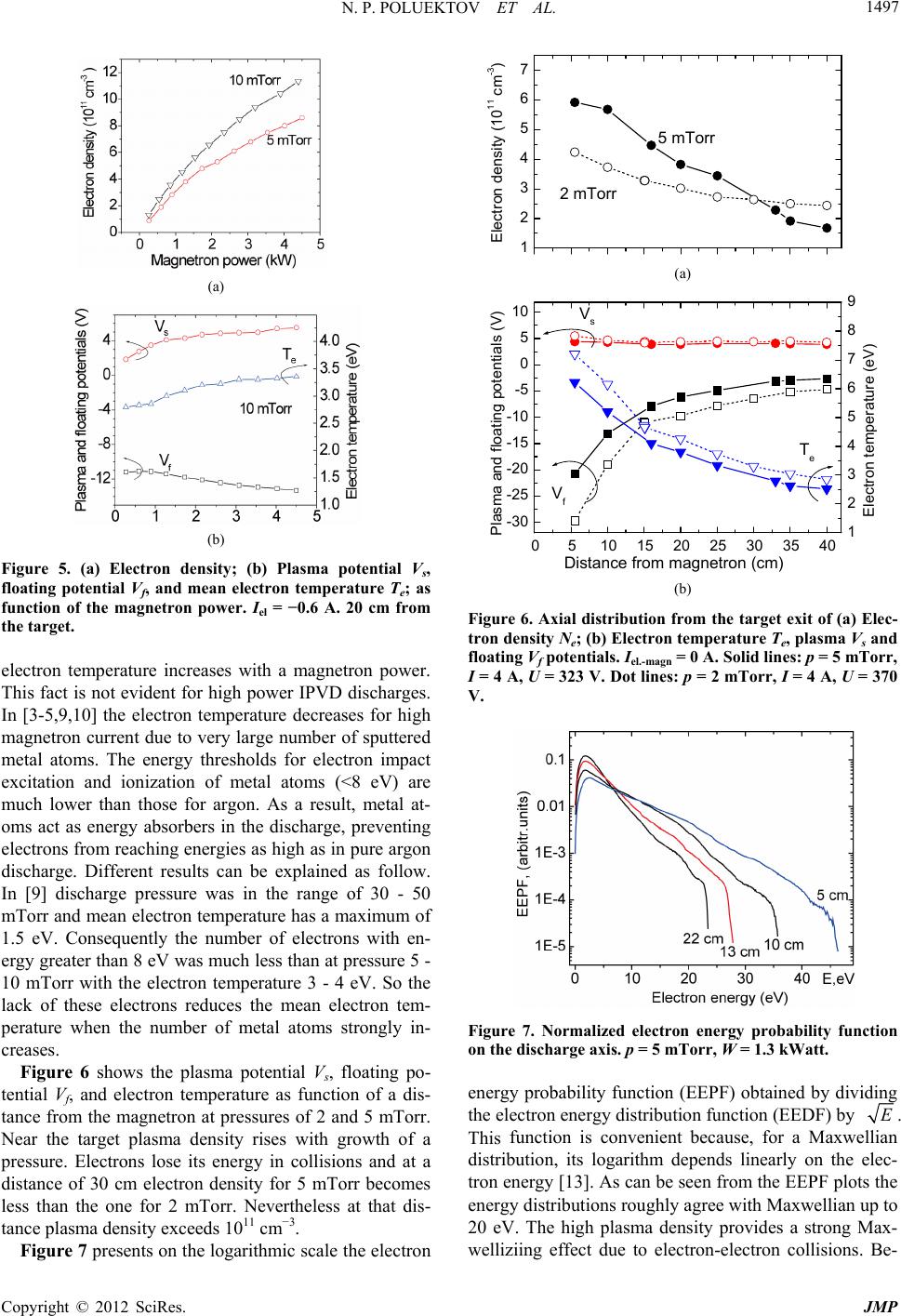 N. P. POLUEKTOV ET AL. 1497 (a) (b) Figure 5. (a) Electron density; (b) Plasma potential Vs, floating potential Vf, and mean electron temperature Te; as function of the magnetron power. Iel = −0.6 A. 20 cm from the target. electron temperature increases with a magnetron power. This fact is not evident for high power IPVD discharges. In [3-5,9,10] the electron temperature decreases for high magnetron current due to very large number of sputtered metal atoms. The energy thresholds for electron impact excitation and ionization of metal atoms (<8 eV) are much lower than those for argon. As a result, metal at- oms act as energy absorbers in the discharge, preventing electrons from reaching energies as high as in pure argon discharge. Different results can be explained as follow. In [9] discharge pressure was in the range of 30 - 50 mTorr and mean electron temperature has a maximum of 1.5 eV. Consequently the number of electrons with en- ergy greater than 8 eV was much less than at pressure 5 - 10 mTorr with the electron temperature 3 - 4 eV. So the lack of these electrons reduces the mean electron tem- perature when the number of metal atoms strongly in- creases. Figure 6 shows the plasma potential Vs, floating po- tential Vf, and electron temperature as function of a dis- tance from the magnetron at pressures of 2 and 5 mTorr. Near the target plasma density rises with growth of a pressure. Electrons lose its energy in collisions and at a distance of 30 cm electron density for 5 mTorr becomes less than the one for 2 mTorr. Nevertheless at that dis- tance plasma density exceeds 1011 cm−3. Figure 7 presents on the logarithmic scale the electron 1 2 3 4 5 6 7 Electron density (1011 cm-3) 5 mTorr 2 mTorr a) (a) 0510 15 20 25 30 35 40 -30 -25 -20 -15 -10 -5 0 5 10 1 2 3 4 5 6 7 8 9 b) Vs Te Vf Plasma and floating potentials (V) Electron temperature (eV) Distance from magnetron (cm) (b) Figure 6. Axial distribution from the target exit of (a) Elec- tron density Ne; (b) Electron temperature Te, plasma Vs and floating Vf potentials. Iel.-magn = 0 A. Solid lines: p = 5 mTorr, I = 4 A, U = 323 V. Dot lines: p = 2 mTorr, I = 4 A, U = 370 V. Figure 7. Normalized electron energy probability function on the discharge axis. p = 5 mTorr, W = 1.3 kWatt. energy probability function (EEPF) obtained by dividing the electron energy distribution function (EEDF) by E. function is convenient because, for a Maxwellian distribution, its logarithm depends linearly on the elec- tron energy [13]. As can be seen from the EEPF plots the energy distributions roughly agree with Maxwellian up to 20 eV. The high plasma density provides a strong Max- welliziing effect due to electron-electron collisions. Be- This Copyright © 2012 SciRes. JMP 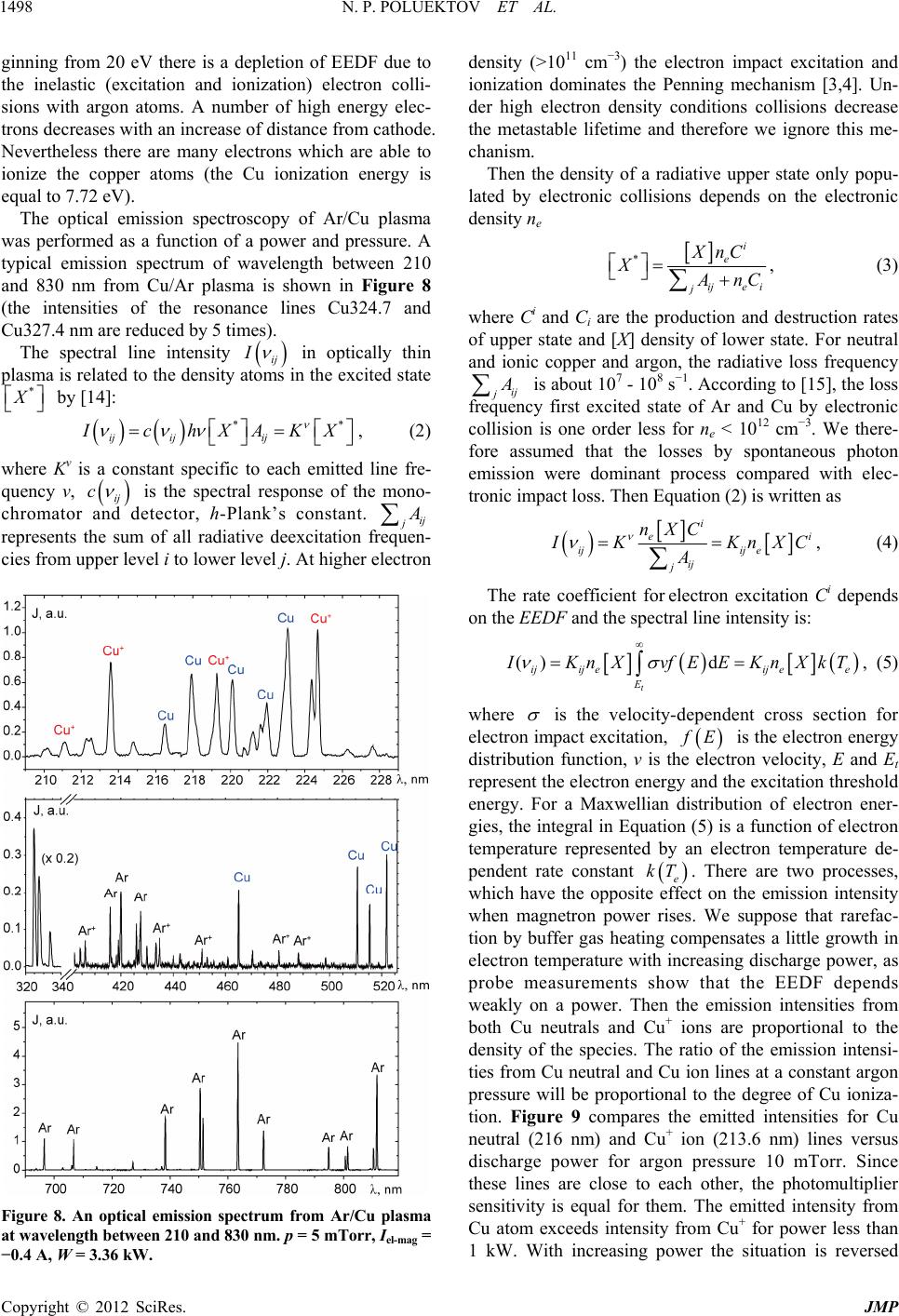 N. P. POLUEKTOV ET AL. 1498 ginning from 20 eV there is a depletion of EEDF due to the inelastic (excitation and ionization) electron colli- sions with argon atoms. A number of high energy elec- trons decreases with an increase of distance from cathode. Nevertheless there are many electrons which are able to ionize the copper atoms (the Cu ionization energy is equal to 7.72 eV). The optical emission spectroscopy of Ar/Cu plasma was performed as a function of a power and pressure. A typical emission spectrum of wavelength between 210 and 830 nm from Cu/Ar plasma is shown in Figure 8 (the intensities of the resonance lines Cu324.7 and Cu327.4 nm are reduced by 5 times). The spectral line intensity ij I in optically thin plasma is related to the density atoms in the excited state * X by [14]: ij ijij ** I chXAKX , (2) where Kν is a constant specific to each emitted line fre- quency ν, ij c is the spectral response of the mono- chromator and detector, h-Plank’s constant. ij j A represents the sum of all radiative deexcitation frequen- cies from upper level i to lower level j. At higher electron Figure 8. An optical emission spectrum from Ar/Cu plasma at wavelength between 210 and 830 nm. p = 5 mTorr, Iel-mag = −0.4 A, W = 3.36 kW. density (>1011 cm−3) the electron impact excitation and ionization dominates the Penning mechanism [3,4]. Un- der high electron density conditions collisions decrease the metastable lifetime and therefore we ignore this me- chanism. Then the density of a radiative upper state only popu- lated by electronic collisions depends on the electronic density ne * i e ije i j XnC X A nC , (3) where Ci and Ci are the production and destruction rates of upper state and [X] density of lower state. For neutral and ionic copper and argon, the radiative loss frequency ij j A is about 107 - 108 s−1. According to [15], the loss frequency first excited state of Ar and Cu by electronic collision is one order less for ne < 1012 cm−3. We there- fore assumed that the losses by spontaneous photon emission were dominant process compared with elec- tronic impact loss. Then Equation (2) is written as i ei ijij e ij j nXC I KKn A XC, (4) The rate coefficient for electron excitation Ci depends on the EEDF and the spectral line intensity is: () d t ijij eij ee E I Kn XvfEEKnXkT , (5) where is the velocity-dependent cross section for electron impact excitation, f E is the electron energy distribution function, v is the electron velocity, E and Et represent the electron energy and the excitation threshold energy. For a Maxwellian distribution of electron ener- gies, the integral in Equation (5) is a function of electron temperature represented by an electron temperature de- pendent rate constant e kT . There are two processes, which have the opposite effect on the emission intensity when magnetron power rises. We suppose that rarefac- tion by buffer gas heating compensates a little growth in electron temperature with increasing discharge power, as probe measurements show that the EEDF depends weakly on a power. Then the emission intensities from both Cu neutrals and Cu+ ions are proportional to the density of the species. The ratio of the emission intensi- ties from Cu neutral and Cu ion lines at a constant argon pressure will be proportional to the degree of Cu ioniza- tion. Figure 9 compares the emitted intensities for Cu neutral (216 nm) and Cu+ ion (213.6 nm) lines versus discharge power for argon pressure 10 mTorr. Since these lines are close to each other, the photomultiplier sensitivity is equal for them. The emitted intensity from Cu atom exceeds intensity from Cu+ for power less than 1 kW. With increasing power the situation is reversed Copyright © 2012 SciRes. JMP 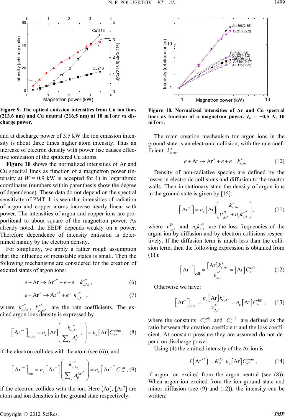 N. P. POLUEKTOV ET AL. 1499 01234 0 20 40 6001234 0 1 2 3 4 Int ensity (arbitrary units) Magne tr on po wer (kW) Cu+213 Cu216 J(Cu+2 13 .6) /J(C u 21 6) Figure 9. The optical emission intensities from Cu ion lines (213.6 nm) and Cu neutral (216.5 nm) at 10 mTorr vs dis- charge power. and at discharge power of 3.5 kW the ion emission inten- sity is about three times higher atom intensity. Thus an increase of electron density with power rise causes effec- tive ionization of the sputtered Cu atoms. Figure 10 shows the normalized intensities of Ar and Cu spectral lines as function of a magnetron power (in- tensity at W = 0.9 kW is accepted for 1) in logarithmic coordinates (numbers within parenthesis show the degree of dependence). These data do not depend on the spectral sensitivity of PMT. It is seen that intensities of radiation of argon and copper atoms increase nearly linear with power. The intensities of argon and copper ions are pro- portional to about square of the magnetron power. As already noted, the EEDF depends weakly on a power. Therefore dependence of intensity emission is deter- mined mainly by the electron density. For simplicity, we apply a rather rough assumption that the influence of metastable states is small. Then the following mechanisms are considered for the creation of excited states of argon ions: * Ar Are ee * ,Ar e k , (6) * Ar Are ** e * ,Are k , (7) where ,Ar e, ,Are are the rate coefficients. The ex- cited argon ions density is expressed by kk * ,Ar atom atom Ar Ar ArAr e ee ij j k nn A C , (8) if the electron collides with the atom (see (6)), and * ,Ar ion ion Ar Ar ArAr e ee ij j k nn A C , (9) if the electron collides with the ion. Here [Ar], [Ar+] are atom and ion densities in the ground state respectively. 11 1 10 0 Intensity (arbitrary units) Magnetron power (kW) Cu21 6(1.23) Ar7504 ( 0.97) Cu2136(2.2) Cu3274( 1.2) Ar8115(0.93) Ar4806(2.35) Cu5106(1.1) Figure 10. Normalized intensities of Ar and Cu spectral lines as function of a magnetron power, Iel = −0.5 A, 10 mTorr. The main creation mechanism for argon ions in the ground state is an electronic collision, with the rate coef- ficient : ,Are k Ar Are ee (10) ,Are k Density of non-radiative species are defined by the losses in electronic collisions and diffusion to the reactor walls. Then in stationary state the density of argon ions in the ground state is given by [15]: ,Ar * , Ar ArAr e eD ee k nnk , (11) where D Ar and * ,ee nk are the loss frequencies of the argon ion by diffusion and by electron collisions respec- tively. If the diffusion term is much less than the colli- sion term, then the following expression is obtained from (11): * ,Arcoll coll , Ar Ar Ar e e kC k (12) Otherwise we have: ,Ar diff diff Ar Ar Ar Ar ee e D nknC , (13) where the constants and are defined as the ratio between the creation coefficient and the loss coeffi- cient. At constant pressure they are assumed do not de- pend on discharge power. coll + Cdiff C Using (4) the emitted intensity of the Ar ion is *Ar ato * Ar Ar ij e IKnC m , (14) if argon ion excited from the argon neutral (see (8)). When argon ion excited from the ion ground state and minor diffusion (see (9) and (12)), the intensity can be written: Copyright © 2012 SciRes. JMP 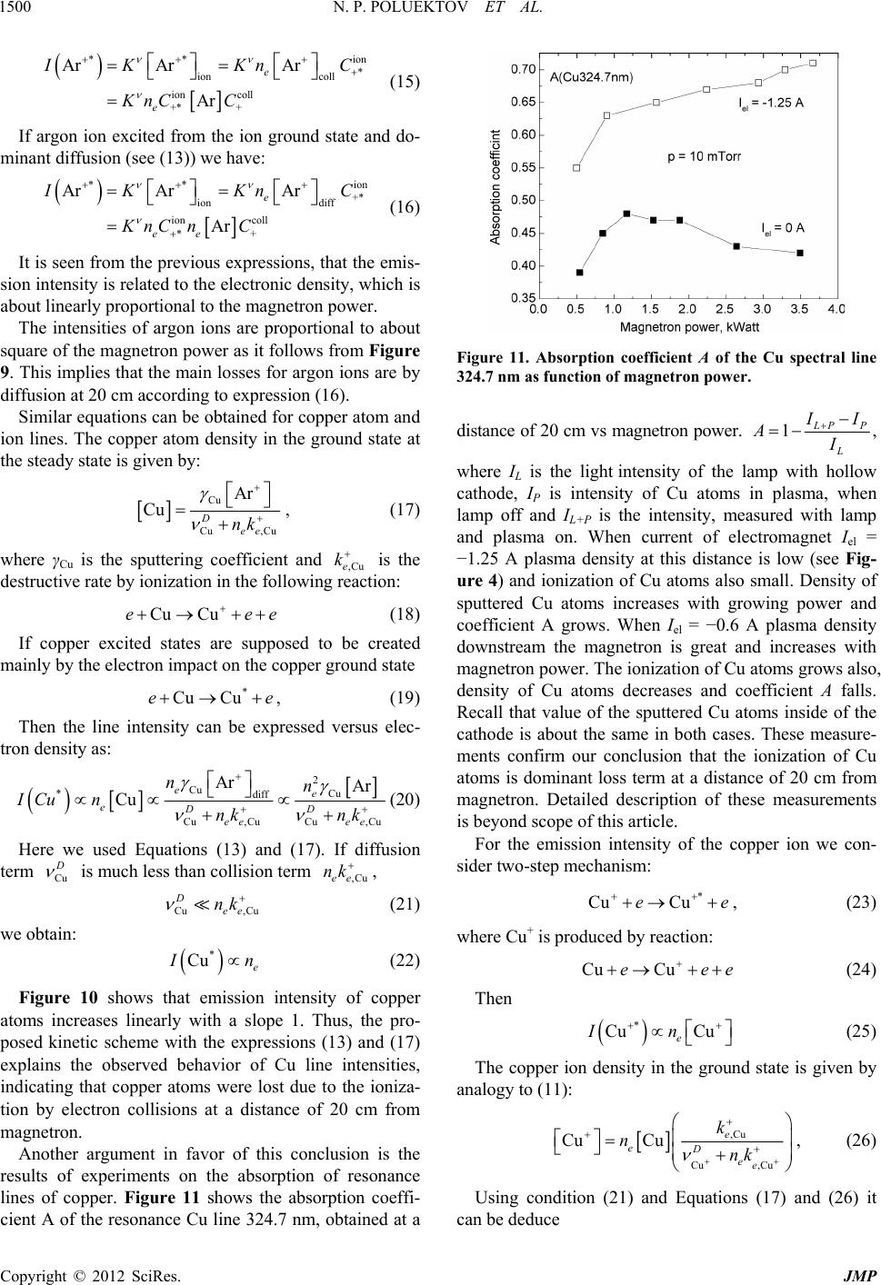 N. P. POLUEKTOV ET AL. 1500 ** * ion coll ion coll +* + Ar ArAr Ar e e ion I KKn KnC C C (15) If argon ion excited from the ion ground state and do- minant diffusion (see (13)) we have: ** +* ion diff ion coll *+ Ar ArAr Ar e ee ion I KKn KnC nC C (16) It is seen from the previous expressions, that the emis- sion intensity is related to the electronic density, which is about linearly proportional to the magnetron power. The intensities of argon ions are proportional to about square of the magnetron power as it follows from Figure 9. This implies that the main losses for argon ions are by diffusion at 20 cm according to expression (16). Similar equations can be obtained for copper atom and ion lines. The copper atom density in the ground state at the steady state is given by: Cu Cu ,Cu Ar Cu D ee nk , (17) where γCu is the sputtering coefficient and ,Cue is the destructive rate by ionization in the following reaction: k Cu Cue ee e (18) If copper excited states are supposed to be created mainly by the electron impact on the copper ground state * Cu Cue , (19) Then the line intensity can be expressed versus elec- tron density as: 2 Cu Cu *diff Cu ,CuCu ,Cu Ar Ar Cu ee eDD ee ee nn ICu nnk nk (20) Here we used Equations (13) and (17). If diffusion term Cu D is much less than collision term , ,Cuee nk Cu ,Cu D ee nk (21) we obtain: * Cu e I n (22) Figure 10 shows that emission intensity of copper atoms increases linearly with a slope 1. Thus, the pro- posed kinetic scheme with the expressions (13) and (17) explains the observed behavior of Cu line intensities, indicating that copper atoms were lost due to the ioniza- tion by electron collisions at a distance of 20 cm from magnetron. Another argument in favor of this conclusion is the results of experiments on the absorption of resonance lines of copper. Figure 11 shows the absorption coeffi- cient A of the resonance Cu line 324.7 nm, obtained at a Figure 11. Absorption coefficient A of the Cu spectral line 324.7 nm as function of magnetron power. distance of 20 cm vs magnetron power. 1 L PP L I I AI , where IL is the light intensity of the lamp with hollow cathode, IP is intensity of Cu atoms in plasma, when lamp off and IL+P is the intensity, measured with lamp and plasma on. When current of electromagnet Iel = −1.25 A plasma density at this distance is low (see Fig- ure 4) and ionization of Cu atoms also small. Density of sputtered Cu atoms increases with growing power and coefficient A grows. When Iel = −0.6 A plasma density downstream the magnetron is great and increases with magnetron power. The ionization of Cu atoms grows also, density of Cu atoms decreases and coefficient A falls. Recall that value of the sputtered Cu atoms inside of the cathode is about the same in both cases. These measure- ments confirm our conclusion that the ionization of Cu atoms is dominant loss term at a distance of 20 cm from magnetron. Detailed description of these measurements is beyond scope of this article. For the emission intensity of the copper ion we con- sider two-step mechanism: * Cu Cue e , (23) where Cu+ is produced by reaction: Cu Cuee e (24) Then * Cu Cu e In (25) The copper ion density in the ground state is given by analogy to (11): ,Cu Cu ,Cu Cu Cue eD ee k nnk , (26) Using condition (21) and Equations (17) and (26) it can be deduce Copyright © 2012 SciRes. JMP 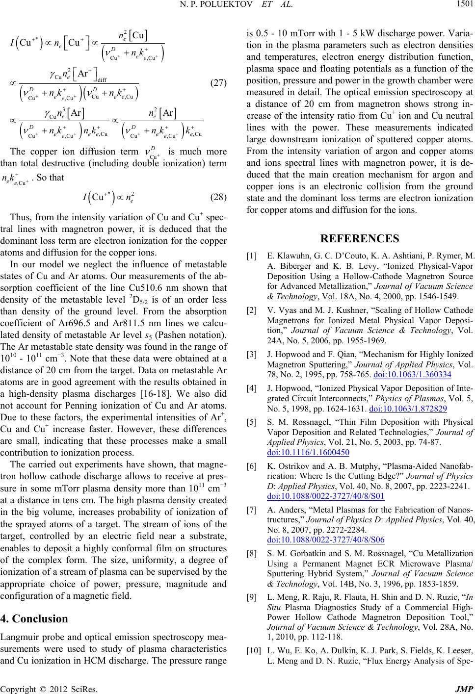 N. P. POLUEKTOV ET AL. 1501 2 * Cu ,Cu 2 Cu diff Cu ,Cu Cu ,Cu 32 Cu ,Cu ,Cu Cu ,CuCu ,Cu Cu CuCu Ar Ar Ar e eD ee e DD eee e ee DD eeeee e n In nk n nk nk nn nk nknk k e (27) The copper ion diffusion term Cu D is much more than total destructive (including double ionization) term ,Cu ee nk . So that * Cu e 2 I n (28) Thus, from the intensity variation of Cu and Cu+ spec- tral lines with magnetron power, it is deduced that the dominant loss term are electron ionization for the copper atoms and diffusion for the copper ions. In our model we neglect the influence of metastable states of Cu and Ar atoms. Our measurements of the ab- sorption coefficient of the line Cu510.6 nm shown that density of the metastable level 2D5/2 is of an order less than density of the ground level. From the absorption coefficient of Ar696.5 and Ar811.5 nm lines we calcu- lated density of metastable Ar level s5 (Pashen notation). The Ar metastable state density was found in the range of 1010 - 1011 cm−3. Note that these data were obtained at a distance of 20 cm from the target. Data on metastable Ar atoms are in good agreement with the results obtained in a high-density plasma discharges [16-18]. We also did not account for Penning ionization of Cu and Ar atoms. Due to these factors, the experimental intensities of Ar+, Cu and Cu+ increase faster. However, these differences are small, indicating that these processes make a small contribution to ionization process. The carried out experiments have shown, that magne- tron hollow cathode discharge allows to receive at pres- sure in some mTorr plasma density more than 1011 cm−3 at a distance in tens cm. The high plasma density created in the big volume, increases probability of ionization of the sprayed atoms of a target. The stream of ions of the target, controlled by an electric field near a substrate, enables to deposit a highly conformal film on structures of the complex form. The size, uniformity, a degree of ionization of a stream of plasma can be supervised by the appropriate choice of power, pressure, magnitude and configuration of a magnetic field. 4. Conclusion Langmuir probe and optical emission spectroscopy mea- surements were used to study of plasma characteristics and Cu ionization in HCM discharge. The pressure range is 0.5 - 10 mTorr with 1 - 5 kW discharge power. Varia- tion in the plasma parameters such as electron densities and temperatures, electron energy distribution function, plasma space and floating potentials as a function of the position, pressure and power in the growth chamber were measured in detail. The optical emission spectroscopy at a distance of 20 cm from magnetron shows strong in- crease of the intensity ratio from Cu+ ion and Cu neutral lines with the power. These measurements indicated large downstream ionization of sputtered copper atoms. From the intensity variation of argon and copper atoms and ions spectral lines with magnetron power, it is de- duced that the main creation mechanism for argon and copper ions is an electronic collision from the ground state and the dominant loss terms are electron ionization for copper atoms and diffusion for the ions. REFERENCES [1] E. Klawuhn, G. C. D’Couto, K. A. Ashtiani, P. Rymer, M. A. Biberger and K. B. Levy, “Ionized Physical-Vapor Deposition Using a Hollow-Cathode Magnetron Source for Advanced Metallization,” Journal of Vacuum Science & Technology, Vol. 18A, No. 4, 2000, pp. 1546-1549. [2] V. Vyas and M. J. Kushner, “Scaling of Hollow Cathode Magnetrons for Ionized Metal Physical Vapor Deposi- tion,” Journal of Vacuum Science & Technology, Vol. 24A, No. 5, 2006, pp. 1955-1969. [3] J. Hopwood and F. Qian, “Mechanism for Highly Ionized Magnetron Sputtering,” Journal of Applied Physics, Vol. 78, No. 2, 1995, pp. 758-765. doi:10.1063/1.360334 [4] J. Hopwood, “Ionized Physical Vapor Deposition of Inte- grated Circuit Interconnects,” Physics of Plasmas, Vol. 5, No. 5, 1998, pp. 1624-1631. doi:10.1063/1.872829 [5] S. M. Rossnagel, “Thin Film Deposition with Physical Vapor Deposition and Related Technologies,” Journal of Applied Physics, Vol. 21, No. 5, 2003, pp. 74-87. doi:10.1116/1.1600450 [6] K. Ostrikov and A. B. Mutphy, “Plasma-Aided Nanofab- rication: Where Is the Cutting Edge?” Journal of Physics D: Applied Physics, Vol. 40, No. 8, 2007, pp. 2223-2241. doi:10.1088/0022-3727/40/8/S01 [7] A. Anders, “Metal Plasmas for the Fabrication of Nanos- tructures,” Journal of Physics D: Applied Physics, Vol. 40, No. 8, 2007, pp. 2272-2284. doi:10.1088/0022-3727/40/8/S06 [8] S. M. Gorbatkin and S. M. Rossnagel, “Cu Metallization Using a Permanent Magnet ECR Microwave Plasma/ Sputtering Hybrid System,” Journal of Vacuum Science & Technology, Vol. 14B, No. 3, 1996, pp. 1853-1859. [9] L. Meng, R. Raju, R. Flauta, H. Shin and D. N. Ruzic, “In Situ Plasma Diagnostics Study of a Commercial High- Power Hollow Cathode Magnetron Deposition Tool,” Journal of Vacuum Science & Technology, Vol. 28A, No. 1, 2010, pp. 112-118. [10] L. Wu, E. Ko, A. Dulkin, K. J. Park, S. Fields, K. Leeser, L. Meng and D. N. Ruzic, “Flux Energy Analysis of Spe- Copyright © 2012 SciRes. JMP  N. P. POLUEKTOV ET AL. Copyright © 2012 SciRes. JMP 1502 cies in Hollow Cathode Magnetron Ionize Physical Vapor Deposition of Copper,” Review of Scientific Instruments, Vol. 81, No. 12, 2010, Article ID: 123502. [11] J. G. Laframboise “Theory of Spherical and Cylindrical Langmuir Probes in a Collisionless Maxwellian Plasma at Rest,” University of Toronto, Toronto, 1966. [12] M. Mausbach, “Parametrization of the Laframboise The- ory for Cylindrical Langmuir Probe Analysis,” Journal of Vacuum Science & Technology, Vol. 15A, No. 6, 1997, pp. 2923-2929. [13] M. A. Lieberman and A. J. Lichtenberg, “Principles of Plasma Discharges and Materials Processing,” Wiley, New York, 1994. [14] R. W. McWhirter, “Spectral Intensities,” In: R. H. Hud- dlestone and S. L. Leonard, Eds., Plasma Diagnostic Te- chniques, Academic, New York, 1965, pp. 165-217. [15] C. Nouvellon, S. Konstantinidis, J. P. Dauchot, M. Wau- telet, P. Y. Jouan, A. Ricard and M. Hecq, “Emission Spectrometry Diagnostic of Sputtered Titanium in Mag- netron Amplified Discharge,” Journal of Applied Physics, Vol. 92, No. 1, 2002, pp. 32-36. doi:10.1063/1.1481780 [16] J. B. Boffard, R. O. Jung, Ch. C. Lin and A. E. Wendt, “Measurement of Metastablt and Resonance Level Densi- ties in Rare-Gas Plasmas by Optical Emission Spectros- copy,” Plasma Sources Science and Technology, Vol. 18, No. 3, 2009, pp. 1-11. doi:10.1088/0963-0252/18/3/035017 [17] G. A. Hebner, “Spatially Resolved, Exited State Densities and Neutral and Ion Temperatures in Inductively Coupled Plasmas,” Journal of Applied Physics, Vol. 80, No. 5, 1996, pp. 2624-2636. doi:10.1063/1.363178 [18] D. Leonhardt, C. R. Eddy, V. A. Shamamian, R. F. Fens- ler and J. E. Butler, “Argon Metastables in a High Den- sity Processing Plasma,” Journal of Applied Physics, Vol. 83, No. 6, 1998, pp. 2971-2978. doi:10.1063/1.367123 |