

Paper Menu >>
Journal Menu >>
 Journal of Modern Physics, 2012, 3, 1490-1493 http://dx.doi.org/10.4236/jmp.2012.310184 Published Online October 2012 (http://www.SciRP.org/journal/jmp) Calibration of GaAlAs Semiconductor Diode S. B. Ota1, Smita Ota1,2 1Institute of Physics, Bhubaneswar, India 2DST Project, DST, New Delhi, India Email: [email protected] Received July 29, 2012; revised September 1, 2012; accepted September 11, 2012 ABSTRACT The forward voltage of GaAlAs semiconductor diode has been measured in the temperature range 50 K - 300 K and for current values between 10 nA and 450 μA. The forward voltage as a function of temperature is least-squares fitted and the coefficients are given. The 1st and 2nd order least-squares fitting has high temperature root between 400 K and 950 K. The presence of the high temperature root indicates that the fitted polynomials are of similar character. The high temperature root is found to increase for the least squares fitted polynomials corresponding to higher current values. Keywords: Semiconductor; Temperature Sensors; GaAlAs 1. Introduction GaAlAs semiconductor diodes have been used in the measurement of low temperatures in the presence of magnetic field. The measurement of low temperature using GaAlAs diodes is based on the usual observation that the voltage across the forward-biased diode increases with decrease in temperature [1-5]. The behavior of the diode has been understood in terms of conduction pri- marily by recombination-generation currents given by the theory of Shockley and coworkers [6]. Below about 50 K, the forward voltage increases more rapidly as the temperature is reduced, which gives rise to a bend in the temperature dependence of forward voltage [7-9]. The diodes are generally calibrated with 10 µA of forward current. The factors among others which decide the use of GaAlAs semiconductor diodes for the measurement of low temperature are sensitivity, linearity, stability, power dissipation and noise [10-16]. The GaAlAs diodes can possibly be used in the ultra low temperature range (0.05 - 1 K) by reducing the forward current to ~10 nA. In cer- tain possible applications of semiconductor diodes for temperature measurement, a high precision in the meas- urement of temperature is needed. Such situations in- clude, the measurement of temperature drift curve in low temperature heat pulse calorimetry [17]. In this article we have studied the calibration of GaAlAs diode and report the coefficients for five decades of current values, 10 nA to 450 μA and in the temperature range 50 K - 300 K. In this paper, we give the temperature dependence of forward voltage of GaAlAs diode for various current values between 10 nA and 450 µA and in the temperature range 50 K to 300 K. The paper is organized as follows. In the following Section 2, the experimental details are given. Section 3 gives the least-squares fittings. The pa- per concludes with the conclusions in Section 4. 2. Experimental Details The measurements were carried out using a computer controlled four-probe setup built around a closed cycle refrigerator [18]. The diode in the CU package configu- ration is epoxied into a flat cylindrical disk and the sen- sor leads are thermally anchored to the same disk. The metal encapsulation of the diode was fixed to the sample space of the closed cycle helium refrigerator with 0.2 mm thick indium foil and a thin layer of Apiezon-N grease by clamping with an aluminum disk with screws using moderate pressure. The leads were further an- chored at the sample space to minimize any thermoelec- tromotive force developed. The temperature of the sam- ple site was controlled using a calibrated type-D silicon diode thermometer in conjunction with a Leybold model LTC60 temperature controller (Leybold AG, Germany). The setup is automated using GPIB-IEEE-488 interface and the control program is written in MSDOS GWBAS- IC. Measurements were carried out between 50 K - 300 K, for forward current from 10 nA to 450 μA. The tem- perature increment was 10 K and the current increment was in 11 equal logarithm interval. Each data point was obtained by averaging 50 reading. A constant current was provided to the GaAlAs diode from a Keithley (Keithley Instruments, USA) model 224/2243 programmable cur- rent source. The forward voltage was measured using a Keithley model 182 sensitive digital voltmeter. C opyright © 2012 SciRes. JMP 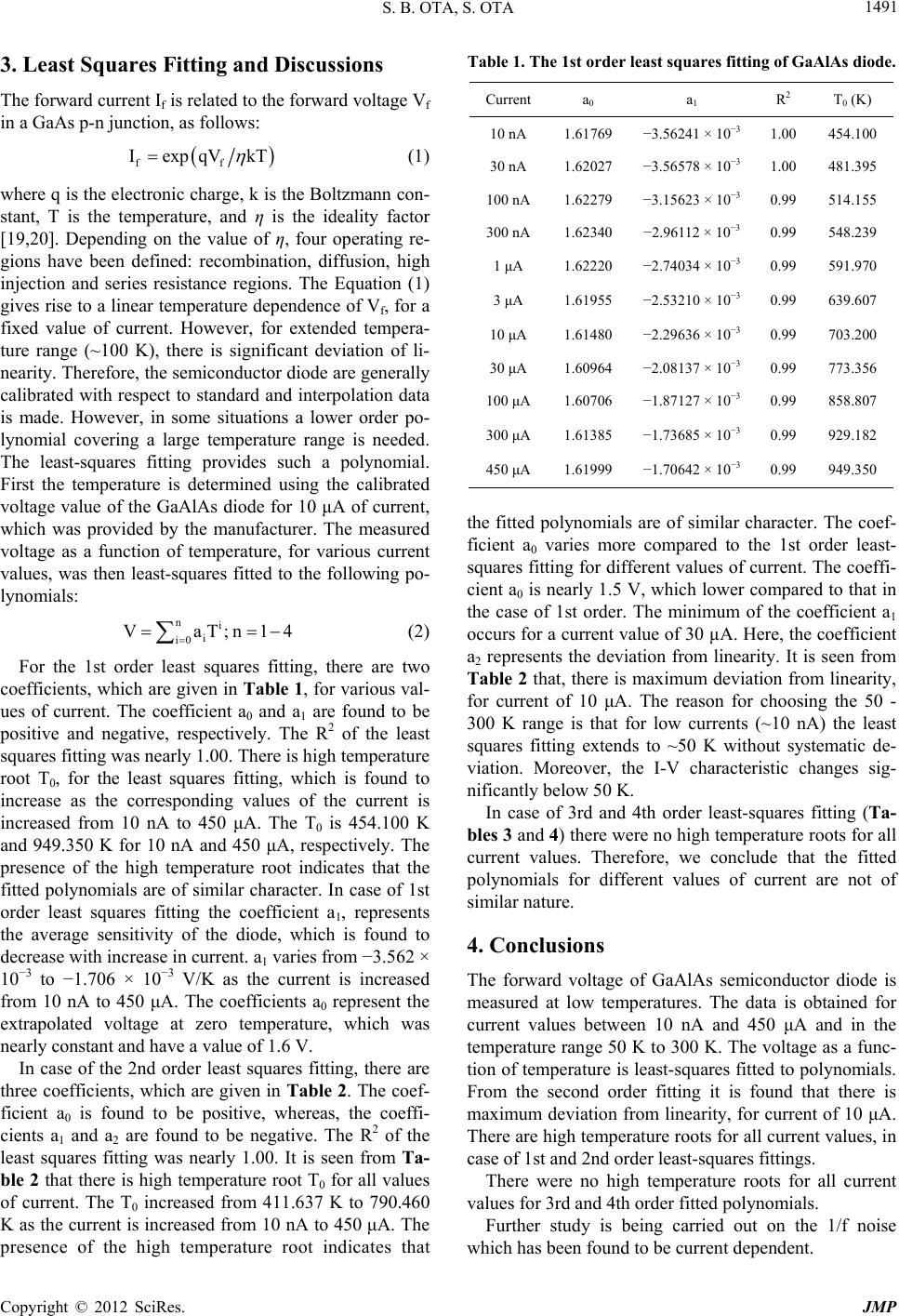 S. B. OTA, S. OTA 1491 3. Least Squares Fitting and Discussions The forward current If is related to the forward voltage Vf in a GaAs p-n junction, as follows: ff IexpqVkT ni iT;n14 (1) where q is the electronic charge, k is the Boltzmann con- stant, T is the temperature, and η is the ideality factor [19,20]. Depending on the value of η, four operating re- gions have been defined: recombination, diffusion, high injection and series resistance regions. The Equation (1) gives rise to a linear temperature dependence of Vf, for a fixed value of current. However, for extended tempera- ture range (~100 K), there is significant deviation of li- nearity. Therefore, the semiconductor diode are generally calibrated with respect to standard and interpolation data is made. However, in some situations a lower order po- lynomial covering a large temperature range is needed. The least-squares fitting provides such a polynomial. First the temperature is determined using the calibrated voltage value of the GaAlAs diode for 10 μA of current, which was provided by the manufacturer. The measured voltage as a function of temperature, for various current values, was then least-squares fitted to the following po- lynomials: i0 Va (2) For the 1st order least squares fitting, there are two coefficients, which are given in Table 1, for various val- ues of current. The coefficient a0 and a1 are found to be positive and negative, respectively. The R2 of the least squares fitting was nearly 1.00. There is high temperature root T0, for the least squares fitting, which is found to increase as the corresponding values of the current is increased from 10 nA to 450 μA. The T0 is 454.100 K and 949.350 K for 10 nA and 450 μA, respectively. The presence of the high temperature root indicates that the fitted polynomials are of similar character. In case of 1st order least squares fitting the coefficient a1, represents the average sensitivity of the diode, which is found to decrease with increase in current. a1 varies from −3.562 × 10⁻³ to −1.706 × 10⁻³ V/K as the current is increased from 10 nA to 450 μA. The coefficients a0 represent the extrapolated voltage at zero temperature, which was nearly constant and have a value of 1.6 V. In case of the 2nd order least squares fitting, there are three coefficients, which are given in Table 2. The coef- ficient a0 is found to be positive, whereas, the coeffi- cients a1 and a2 are found to be negative. The R2 of the least squares fitting was nearly 1.00. It is seen from Ta- ble 2 that there is high temperature root T0 for all values of current. The T0 increased from 411.637 K to 790.460 K as the current is increased from 10 nA to 450 μA. The presence of the high temperature root indicates that Table 1. The 1st order least squares fitting of GaAlAs diode. Current a0 a1 R2 T0 (K) 10 nA 1.61769 −3.56241 × 10⁻³ 1.00 454.100 30 nA 1.62027 −3.56578 × 10⁻³ 1.00 481.395 100 nA 1.62279 −3.15623 × 10⁻³ 0.99 514.155 300 nA 1.62340 −2.96112 × 10⁻³ 0.99 548.239 1 μA 1.62220 −2.74034 × 10⁻³ 0.99 591.970 3 μA 1.61955 −2.53210 × 10⁻³ 0.99 639.607 10 μA 1.61480 −2.29636 × 10⁻³ 0.99 703.200 30 μA 1.60964 −2.08137 × 10⁻³ 0.99 773.356 100 μA 1.60706 −1.87127 × 10⁻³ 0.99 858.807 300 μA 1.61385 −1.73685 × 10⁻³ 0.99 929.182 450 μA 1.61999 −1.70642 × 10⁻³ 0.99 949.350 the fitted polynomials are of similar character. The coef- ficient a0 varies more compared to the 1st order least- squares fitting for different values of current. The coeffi- cient a0 is nearly 1.5 V, which lower compared to that in the case of 1st order. The minimum of the coefficient a1 occurs for a current value of 30 µA. Here, the coefficient a2 represents the deviation from linearity. It is seen from Table 2 that, there is maximum deviation from linearity, for current of 10 μA. The reason for choosing the 50 - 300 K range is that for low currents (~10 nA) the least squares fitting extends to ~50 K without systematic de- viation. Moreover, the I-V characteristic changes sig- nificantly below 50 K. In case of 3rd and 4th order least-squares fitting (Ta- bles 3 and 4) there were no high temperature roots for all current values. Therefore, we conclude that the fitted polynomials for different values of current are not of similar nature. 4. Conclusions The forward voltage of GaAlAs semiconductor diode is measured at low temperatures. The data is obtained for current values between 10 nA and 450 μA and in the temperature range 50 K to 300 K. The voltage as a func- tion of temperature is least-squares fitted to polynomials. From the second order fitting it is found that there is maximum deviation from linearity, for current of 10 μA. There are high temperature roots for all current values, in case of 1st and 2nd order least-squares fittings. There were no high temperature roots for all current values for 3rd and 4th order fitted polynomials. Further study is being carried out on the 1/f noise which has been found to be crrent dependent. u Copyright © 2012 SciRes. JMP 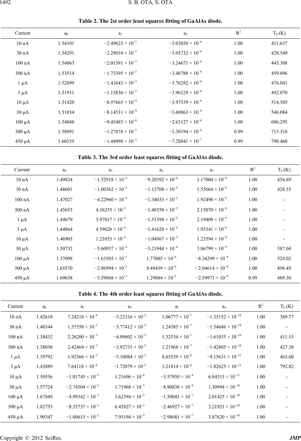 S. B. OTA, S. OTA Copyright © 2012 SciRes. JMP 1492 Table 2. The 2st order least squares fitting of GaAlAs diode. Current a0 a1 a2 R2 T0 (K) 10 nA 1.54101 −2.49623 × 10⁻³ −3.03030 × 10⁻⁶ 1.00 411.637 30 nA 1.54291 −2.29010 × 10⁻³ −3.05732 × 10⁻⁶ 1.00 428.549 100 nA 1.54063 −2.01391 × 10⁻³ −3.24671 × 10⁻⁶ 1.00 445.308 300 nA 1.53514 −1.73395 × 10⁻³ −3.48788 × 10⁻⁶ 1.00 459.896 1 μA 1.52699 −1.41643 × 10⁻³ −3.76282 × 10⁻⁶ 1.00 476.041 3 μA 1.51931 −1.13836 × 10⁻³ −3.96129 × 10⁻⁶ 1.00 492.070 10 μA 1.51420 −8.97665 × 10⁻⁴ −3.97539 × 10⁻⁶ 1.00 514.505 30 μA 1.51854 −8.14531 × 10⁻⁴ −3.60063 × 10⁻⁶ 1.00 546.084 100 μA 1.54048 −9.45485 × 10⁻⁴ −2.63127 × 10⁻⁶ 1.00 606.295 300 μA 1.58091 −1.27878 × 10⁻³ −1.30194 × 10⁻⁶ 0.99 715.318 450 μA 1.60155 −1.44998 × 10⁻³ −7.28841 × 10⁻⁷ 0.99 790.460 Table 3. The 3rd order least squares fitting of GaAlAs diode. Current a0 a1 a2 a3 R2 T0 (K) 10 nA 1.49824 −1.52918 × 10⁻³ −9.20392 × 10⁻⁶ 1.17004 × 10⁻⁸ 1.00 454.69 30 nA 1.48601 −1.00362 × 10⁻³ −1.12708 × 10⁻⁵ 1.55664 × 10⁻⁸ 1.00 428.55 100 nA 1.47027 −4.22960 × 10⁻⁴ −1.34033 × 10⁻⁵ 1.92490 × 10⁻⁸ 1.00 - 300 nA 1.45653 4.36255 × 10⁻⁵ −1.48359 × 10⁻⁵ 2.15070 × 10⁻⁸ 1.00 - 1 μA 1.44679 3.97017 × 10⁻⁴ −1.53398 × 10⁻⁵ 2.19409 × 10⁻⁸ 1.00 - 3 μA 1.44864 4.59626 × 10⁻⁴ −1.41628 × 10⁻⁵ 1.93341 × 10⁻⁸ 1.00 - 10 μA 1.46903 1.23853 × 10⁻⁴ −1.04967 × 10⁻⁵ 1.23594 × 10⁻⁸ 1.00 - 30 μA 1.50732 −5.60957 × 10⁻⁴ −5.21944 × 10⁻⁶ 3.06799 × 10⁻⁹ 1.00 587.04 100 μA 1.57098 −1.63505 × 10⁻³ 1.77085 × 10⁻⁶ −8.34299 × 10⁻⁹ 1.00 524.02 300 μA 1.65570 −2.96994 × 10⁻³ 9.49439 × 10⁻⁶ −2.04614 × 10⁻⁸ 1.00 498.49 450 μA 1.69658 −3.59868 × 10⁻³ 1.29884 × 10⁻⁵ −2.59971 × 10⁻⁸ 0.99 489.30 Table 4. The 4th order least squares fitting of GaAlAs diode. Current a0 a1 a2 a3 a4 R2 T0 (K) 10 nA 1.42610 7.24218 × 10⁻⁴ −3.23316 × 10⁻⁵ 1.06777 × 10⁻⁷ −1.35152 × 10⁻¹⁰ 1.00 389.77 30 nA 1.40344 1.57558 × 10⁻³ −3.77412 × 10⁻⁵ 1.24385 × 10⁻⁷ −1.54686 × 10⁻¹⁰ 1.00 - 100 nA 1.38432 2.26200 × 10⁻³ −4.09602 × 10⁻⁵ 1.32534 × 10⁻⁷ −1.61035 × 10⁻¹⁰ 1.00 411.15 300 nA 1.38030 2.42464 × 10⁻³ −3.92733 × 10⁻⁵ 1.21968 × 10⁻⁷ −1.42805 × 10⁻¹⁰ 1.00 427.38 1 μA 1.39792 1.92366 × 10⁻³ −3.10084 × 10⁻⁵ 8.63539 × 10⁻⁸ −9.15631 × 10⁻¹¹ 1.00 463.60 3 μA 1.43889 7.64118 × 10⁻⁴ −1.72879 × 10⁻⁵ 3.21814 × 10⁻⁸ −1.82625 × 10⁻¹¹ 1.00 792.82 10 μA 1.50556 −1.01745 × 10⁻³ 1.21696 × 10⁻⁶ −3.57950 × 10⁻⁸ 6.84515 × 10⁻¹¹ 1.00 - 30 μA 1.57724 −2.74504 × 10⁻³ 1.71968 × 10⁻⁵ −8.90838 × 10⁻⁸ 1.30994 × 10⁻¹⁰ 1.00 - 100 μA 1.67849 −4.99342 × 10⁻³ 3.62394 × 10⁻⁵ −1.50041 × 10⁻⁷ 2.01425 × 10⁻¹⁰ 1.00 - 300 μA 1.82753 −8.33737 × 10⁻³ 6.45827 × 10⁻⁵ −2.46927 × 10⁻⁷ 3.21921 × 10⁻¹⁰ 1.00 - 450 μA 1.90347 −1.00615 × 10⁻² 7.93194 × 10⁻⁵ −2.98681 × 10⁻⁷ 3.87620 × 10⁻¹⁰ 1.00 -  S. B. OTA, S. OTA 1493 5. Acknowledgements The author is benefited from his visit to Europe in 1988-1992 for HTSC research, Xiamen, China during 1995 for statistical physics conference and New Orleans, USA during 2008 for APS March meeting. We ac- knowledge Dr. C. Iannicello and others of American In- stitute of Physics for providing access to the URL of AIP UniPHY. REFERENCES [1] H. Harris, “Concerning a Thermometer Made with Solid- State Diodes,” Scientific American, Vol. 204, No. 6, 1961, p. 192. [2] A. G. McNamara, “Semiconductor Diodes and Transis- tors as Electrical Thermometers,” Review of Scientific In- struments, Vol. 33, No. 3, 1962, pp. 330-333. doi:10.1063/1.1717834 [3] B. G. Cohen, W. B. Snow and A. R. Tretola, “GaAs p-n Junction Diodes for Wide Range Thermometry,” Review of Scientific Instruments, Vol. 34, No. 10, 1963, pp. 1091- 1093. doi:10.1063/1.1718140 [4] J. Unsworth and A. C. Rose-Innes, “Silicon p-n Junctions as Low Temperature Thermometers,” Cryogenics, Vol. 6, No. 4, 1966, pp. 239-240. doi:10.1016/0011-2275(66)90101-9 [5] G. K. White, “Experimental Techniques in Low-Tem- perature Physics,” Clarendon Press, Oxford, 1979, p. 115. [6] C. T. Saha, R. N. Noyce and W. Shockley, “Carrier Gen- eration and Recombination in p-n Junctions and p-n Junc- tion Characteristics,” Proceedings of the IRE, Vol. 45, No. 9, 1957, pp. 1228-1243. doi:10.1109/JRPROC.1957.278528 [7] S. B. Ota and S. Ota, “A Study of Forward Characteris- tics of a GaAlAs Temperature Sensor Diode,” Measure- ment Science and Technology, Vol. 11, No. 6, 2000, p. 815. doi:10.1088/0957-0233/11/6/327 [8] S. B. Ota and S. Ota, “Thermometry between 10 - 300 K Using GaAlAs Diode,” Modern Physics Letter B, Vol. 14, No. 11, 2000, p. 393. doi:10.1142/S0217984900000549 [9] S. B. Ota, J. Bascuňán and S. Ota, “Low Temperature Characteristic of GaAlAs TEmperature Sensor Diode,” Modern Physics Letter B, Vol. 15, No. 9, 2001, p. 319. doi:10.1142/S0217984901001744 [10] J. Verperk and P. Strnad, “Stability of Silicon Diodes as Temperature Sensors in the Range 4.2 - 273 K,” Cryo- genics, Vol. 24, 1984, pp. 245-248. [11] E. Gmelin and W. Heinke, “Cryostat for Spatial and Spectral Luminescence Experiments,” Cryogenics, 1976, pp. 614-615. [12] Yu. M. Shwarts, et al., “Radiation-Resistant Silicon Di- ode Temperature Sensors,” Sensors and Actuators A: Physical, Vol. 97-98, 2002, pp. 271-279. doi:10.1016/S0924-4247(01)00874-3 [13] V. L. Borblik, et al., “About Manifestation of the Piezo- junction Effect in Diode Temperature Sensors,” Semi. Phys. Quantum Elec. Optoelec., Vol. 6, No. 1, 2003, pp. 97-101. [14] V. N. Sokolov and Yu. M. Shwarts, “Effect of Nonuni- form Doping Profile on Thermometric Performance of Diode Temperature Sensors,” Semi. Phys. Quantum Elec. Optoelec., Vol. 5, No. 2, 2002, pp. 201-211. [15] P. S. Iskrenovic and D. B. Mitic, “Assortment of Optimal Conditions for Running the Impulse Diode Thermome- ter,” Review of Scientific Instruments, Vol. 65, No. 2, 1994, p. 477. doi:10.1063/1.1145160 [16] P. S. Iskrenovic, “Systematic Error of Diode Thermome- ter,” Review of Scientific Instruments, Vol. 80, No. 8, 2009, Article ID: 084901. doi:10.1063/1.3202102 [17] E. Gmelin and K. Ripka, “A Simple Versatile Sample Holder of Low Heat Capacity for Adiabetic Calorimetry,” Cryogenics, Vol. 21, No. 2, 1981, pp. 117-118. doi:10.1016/0011-2275(81)90061-8 [18] S. B. Ota and S. Ota, “On the Ideality Factor of the GaAlAs Semiconductor Diode below Knee Voltage,” Modern Physics Letter B, Vol. 21, No. 19, 2007, p. 1235. doi:10.1142/S0217984907013602 [19] S. Yoshida, et al., “Microscopic Basis for the Mechanism of Carrier Dynamics in an Operating p-n Junction Exam- ined by Using Light-Modulated Scanning Tunneling Spectroscopy,” Physical Review Letters, Vol. 98, No. 2, 2007, Article ID: 26802. doi:10.1103/PhysRevLett.98.026802 [20] L. Kirkup, et al., “Effect of Injection Current on the Re- peatability of Laser Diode Junction Voltage-Temperature Measurements,” Journal of Applied Physics, Vol. 101, No. 2, 2007, Article ID: 23118. doi:10.1063/1.2427097 Copyright © 2012 SciRes. JMP |