

Paper Menu >>
Journal Menu >>
 Creative Education 2012. Vol.3, Special Issue, 856-858 Published Online October 2012 in SciRes (http://www.SciRP.org/journal/ce) http://dx.doi.org/10.4236/ce.2012.326128 Copyright © 2012 SciRes. 856 Undergraduate Curriculum Development for Digital Integrated Circuit Design Xin Chen Department of Electronic Science and Technology, Tongji University, Shanghai, China Email: [email protected] Received August 29th, 2012; revised September 3 0th, 2012; accepted Octob e r 11th, 2012 This article describes the development of a Digital Integrated Circuit Design curriculum, which includes how to select the design level and how to implement the design. The curriculum is for the undergraduates in grade four, whose major is microelectronics. The development is in the background of very large scale integrated circuits. Since the popular design flow is a hierarchy of abstraction levels, the goal of the cur- riculum is to develop the students’ ability to design an actual circuit from scratch. Comparison is provided from two aspects. The first aspect is the contents of various published textbooks. The second aspect is the contents of similar courses in famous universities. Keywords: Digital Integrated Circuit; Design Abstraction Level; Transistor Level; Gate Level; Hardware Description Language Introduction Microelectronics is the base for modern information tech- nology. And the digital integrated circuits are those who are based on binary computation, which are the compositions for microprocessors and communication circuits. Currently, a digital integrated circuit may include thousands of million transistors. For such a complicate design, design method applies the abstraction level concept into the design flow. According to specific design requirement, proper abstrac- tion level (or levels) will be used to fulfill the design task. Ac- cording to the increase order of the abstraction degree, the lev- els are device, circuit, gate, functional module, and system, as shown in Figure 1 (Rabaey et al., 2003). For undergraduates whose major is microelectronics, and have finished merits in device curriculum, circuit level is the next higher abstraction level for them to explore. Gate level is the most popular thing to study for microelectronic undergraduates in the past due to the standard parts for gates or latches. Modular or systematic design is studied in other curricula, such as Digital Logic, or Computer Architecture, since it uses different strategies from the formers’. With ASICs replaced standard parts, circuit level design becomes very important in microelectronic industry. Circuit level design is mostly proprietary to microelectronic scope, since it needs knowledge of transistors, which will not in detail be studied for majors other than micro electronics. On the other hand, a digital integrated circuit can be imple- mented on a chip sized in several square millimeters, which can be a central processing system (Lai et al., 2008). For under- graduate curriculum, they do not need to do such a complex design that a module, such as adder or multiplier (Purohit et al., 2009), will fit in their level. For implementation, there are mul- tiple choices according to which kind of manufacturers you choose. Nowadays, standard-cell and FPGA (Field Program- mable Gate Array) based designs are popular due to their ability to implement efficient design in performance or time-to-market when compared to other approaches (Fey et al., 1989; Kriete et al., 1984; Reis, et al., 1988; Nelson, 2008). Specifically, teach- ers teach standard-cell designs to let students get to know the manufacturers, and FPGA design to know its design tools ac- cording to their nature . This paper is in 4 sections. The 1st part is this introduction. The 2nd part presents the contents of the curricula. The 3rd part introduces the project phase of the curriculum. The 4th part is conclusion. Contents of the Curriculum Contents of Textbooks Written by Famous Professors in the World With the copyright of those textbooks, some publishing houses in time pressed textbooks for digital integrated circuits design in both English and Chinese, such as “Digital Integrated Circuits—A Design Perspective, 2nd Edition”, and its Chinese version. Here we use this book in transistor level design, since it introduces fundamental circuit cells from transistor equations, which in a way similar to that of an analog integrated circuit (Rabaey, 2003). Other book, such as “Digital Circuit Analysis and Design with Simulink Modeling”, introduces digital inte- grated circuits design from the view of digital logic and CPLD (Complex Programmable Logic Device) or FPGA (Field Pro- grammable Gate Array) (Karris, 2007). There are also books for design flow, such as “Digital Integrated Circuit Design: From VLSI Architectures to CMOS Fabrication” (Kaeslin, 2008). Contents of Similar Courses in Other Universities In University of British Columbia, course of Digital Systems Design is based on the VHDL Hardware Description Language. They will show how VHDL can be used to specify very large systems at the modular or systematic level. And they have a graduate level course for overview of deep submicron custom 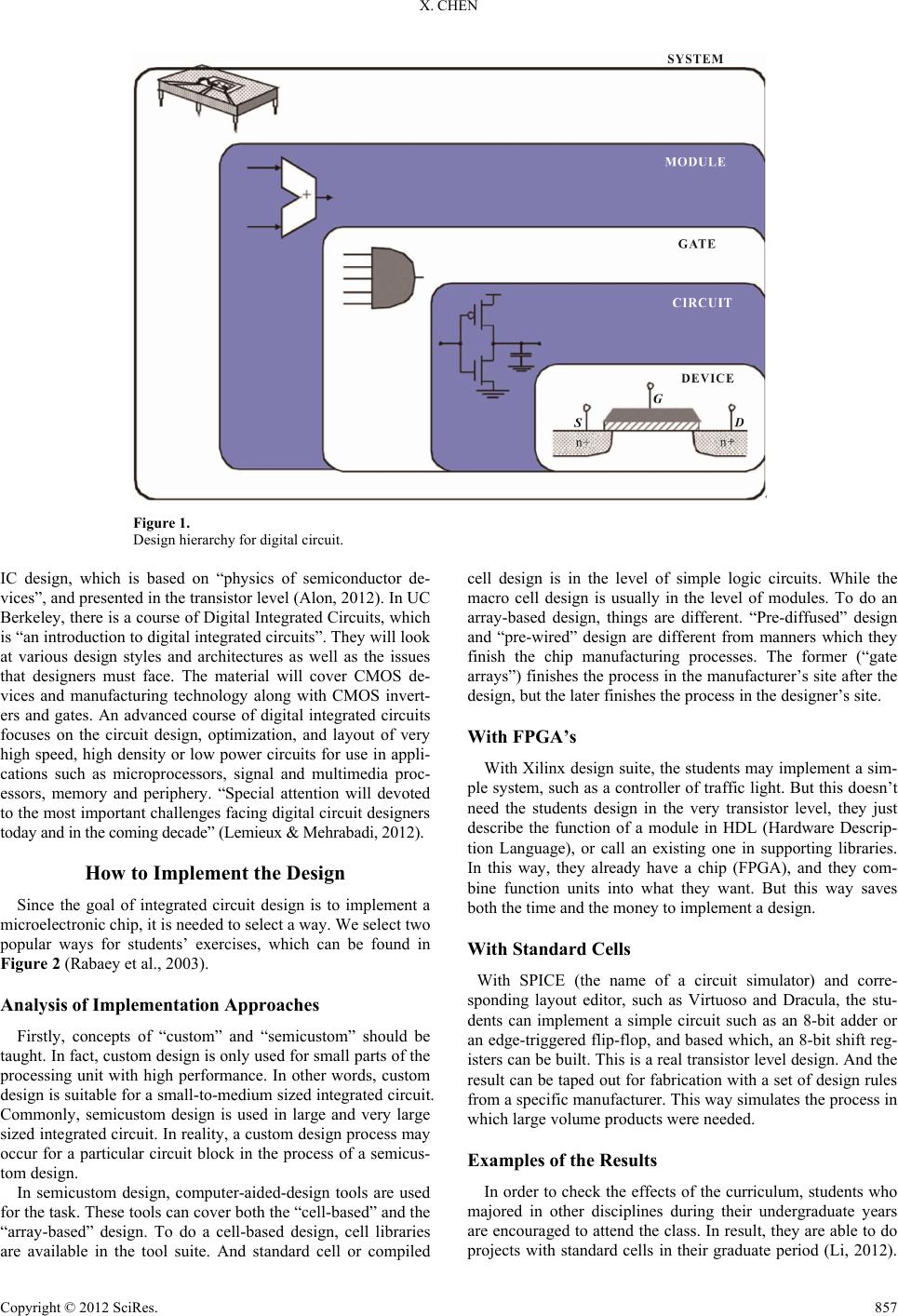 X. CHEN Figure 1. Design hierarchy for digital circuit. IC design, which is based on “physics of semiconductor de- vices”, and presented in the transistor level (Alon, 2012). In UC Berkeley, there is a course of Digital Integrated Circuits, which is “an introduction to digital integrated circuits”. They will look at various design styles and architectures as well as the issues that designers must face. The material will cover CMOS de- vices and manufacturing technology along with CMOS invert- ers and gates. An advanced course of digital integrated circuits focuses on the circuit design, optimization, and layout of very high speed, high density or low power circuits for use in appli- cations such as microprocessors, signal and multimedia proc- essors, memory and periphery. “Special attention will devoted to the most important challenges facing digital circuit designers today and in the coming decade” (Lemieux & Mehrabadi, 2012). How to Implement the Design Since the goal of integrated circuit design is to implement a microelectronic chip, it is needed to select a way. We select two popular ways for students’ exercises, which can be found in Figure 2 (Rabaey et al., 2003). Analysis of Implementation Approaches Firstly, concepts of “custom” and “semicustom” should be taught. In fact, custom design is only used for small parts of the processing unit with high performance. In other words, custom design is suitable for a small-to-medium sized integrated circuit. Commonly, semicustom design is used in large and very large sized integrated circuit. In reality, a custom design process may occur for a particular circuit block in the process of a semicus- tom design. In semicustom design, computer-aided-design tools are used for the task. These tools can cover both the “cell-based” and the “array-based” design. To do a cell-based design, cell libraries are available in the tool suite. And standard cell or compiled cell design is in the level of simple logic circuits. While the macro cell design is usually in the level of modules. To do an array-based design, things are different. “Pre-diffused” design and “pre-wired” design are different from manners which they finish the chip manufacturing processes. The former (“gate arrays”) finishes the process in the manufacturer’s site after the design, but the later finishes the process in the designer’s site. With FPGA’s With Xilinx design suite, the students may implement a sim- ple system, such as a controller of traffic light. But this doesn’t need the students design in the very transistor level, they just describe the function of a module in HDL (Hardware Descrip- tion Language), or call an existing one in supporting libraries. In this way, they already have a chip (FPGA), and they com- bine function units into what they want. But this way saves both the time and the money to implement a design. With Sta ndard Ce lls With SPICE (the name of a circuit simulator) and corre- sponding layout editor, such as Virtuoso and Dracula, the stu- dents can implement a simple circuit such as an 8-bit adder or an edge-triggered flip-flop, and based which, an 8-bit shift reg- isters can be built. This is a real transistor level design. And the result can be taped out for fabrication with a set of design rules from a specific manufacturer. This way simulates the process in which large volume products were needed. Examples of the Results In order to check the effects of the curriculum, students who majored in other disciplines during their undergraduate years are encouraged to attend the class. In result, they are able to do projects with standard cells in their graduate period (Li, 2012). Copyright © 2012 SciRes. 857 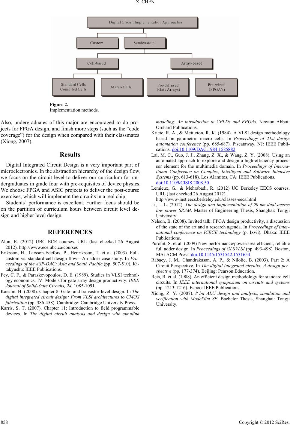 X. CHEN Figure 2. Implementation methods. Also, undergraduates of this major are encouraged to do pro- jects for FPGA design, and finish more steps (such as the “code coverage”) for the design when compared with their classmates (Xiong, 2007). Results Digital Integrated Circuit Design is a very important part of microelectronics. In the abstraction hierarchy of the design flow, we focus on the circuit level to deliver our curriculum for un- dergraduates in grade four with pre-requisites of device physics. We choose FPGA and ASIC projects to deliver the post-course exercises, which will implement the circuits in a real chip. Students’ performance is excellent. Further focus should be on the partition of curriculum hours between circuit level de- sign and higher level design. REFERENCES Alon, E. (2012) UBC ECE courses. URL (last checked 26 August 2012). http://www.ece.ubc.ca/courses Eriksson, H., Larsson-Edefors, P., Henriksson, T. et al. (2003). Full- custom vs. standard-cell design flow—An adder case study. In Pro- ceedings of the ASP-DAC: Asia and South Pacific (pp. 507-510). Ki- takyushu: IEEE Publications. Fey, C. F., & Paraskevopoulos, D. E. (1989). Studies in VLSI technol- ogy economics. IV: Models for gate array design productivity. IEEE Journal of Solid-State Circuits, 24, 1085-1091. Kaeslin, H. (2008). Chapter 8: Gate- and transistor-level design. In The digital integrated circuit design: From VLSI architectures to CMOS fabrication (pp. 386-458). Cambridge: Cam bridge University Pr es s . Karris, S. T. (2007). Chapter 11: Introduction to field programmable devices. In The digital circuit analysis and design with simulink modeling: An introduction to CPLDs and FPGAs. Newton Abbot: Orchard Publications. Kriete, R. A., & Mettleton. R. K. (1984). A VLSI design methodology based on parametric macro cells. In Proceedings of 21st design automation conference (pp. 685-687). Piscataway, NJ: IEEE Publi- cations. doi:10.1109/DAC.1984.1585882 Lai, M. C., Guo, J. J., Zhang, Z. X., & Wang, Z. Y. (2008). Using an automated approach to explore and design a high-efficiency proces- sor element for the multimedia domain. In Proceedings of Interna- tional Conference on Complex, Intelligent and Software Intensive Systems (pp. 613-618). Los A lamitos, CA: IEEE P ublications. doi:10.1109/CISIS.2008.50 Lemieux, G., & Mehrabadi, R. (2012) UC Berkeley EECS courses. URL (last checked 26 August 2012). http://www-inst.eecs.berkeley.edu/classes-eecs.html Li, L. L. (2012). The design and implementation of 90 nm dual-access low power SRAM. Master of Engineering Thesis, Shanghai: Tongji University Nelson, B. (2008). Invited talk: FPGA design productivity, a discussion of the state of the art and a research agenda. In Proceedings of inter- national conference on ICECE technology (p. Ixvii). Dhaka: IEEE Publications. Purohit, S. et al. (2009) New performance/power/area efficient, reliable full adder design. In Proceedings of GLSVLSI (pp. 493-498). Boston, MA: ACM Press. doi:10.1145/1531542.1531654 Rabaey, J. M., Chandrakasan, A. P., & Nilolic, B. (2003). Part 2: A Circuit Perspective. In The digital integrated circuits: A design per- spective (pp. 177-374). Beijing: Pearson Education. Reis, R. et al. (1988). An efficient design methodology for standard cell circuits. In IEEE international symposium on circuits and systems (pp. 1213-1216). Espoo: IEEE Publications. Xiong, Z. Y. (2007). 8-bit ALU design and analysis, simulation and verification with ModelSim SE. Bachelor Thesis, Shanghai: Tongji University. Copyright © 2012 SciRes. 858 |