

Paper Menu >>
Journal Menu >>
 Journal of Surface Engineered Materials and Advanced Technology, 2012, 2, 264-270 http://dx.doi.org/10.4236/jsemat.2012.24040 Published Online October 2012 (http://www.SciRP.org/journal/jsemat) E-Beam Graft Polymerization of Hydrophilic PEG-Methacrylate on the Surface of PMMA Seong-Cheol Kim1, PilHo Huh2* 1Department of Nano, Medical and Polymer Materials, Yeungnam Univeristy, Gyeongsan, Republic of Korea; 2Solar Energy R&D Center, Samsung Electronics Co., Ltd., Yongin, Republic of Korea. Email: *[email protected] Received July 23rd, 2012; revised August 29th, 2012; accepted September 9th, 2012 ABSTRACT The graft polymerization of hydrophilic monomers on the surface of hydrophobic PMMA was performed using an elec- tron beam (e-beam). The dose of e-beam irradiation, reaction concentration, temperature, and reaction time were used to study the effect of variables on the graft density of poly (ethylene glycol)-methacrylate. The results demonstrated that the weight percentage of graft polymer increased with increasing temperature, time and monomer concentration. How- ever, the weight of the graft polymer did not increase with the increasing dose of e-beam irradiation. The change of the contact angle of the water droplet on the PMMA surface was monitored as a function of a reaction time. The results showed that the contact angle decreased up until a specific time and then leveled off to an approximately constant value after a certain reaction time of the graft polymerization. Transmission electron microscopy proved that the constant value of the contact angle was due to the local survival of surface radicals followed by the perpendicular diffusion of monomers only into the bulk of the surface-modified area on the sheet surface. Keywords: Electron Beam; Surface Graft; Contact Angle; ATR; TEM 1. Introduction The modifications of the surface of materials such as commercial films and biomedical materials have at- tracted many researchers and industrialists due to the dramatic changes in the original physical properties [1-4]. New material properties such as the self-cleaning of sur- faces including fingerprint-free protection films for cell phones, and antimicrobial and antistatic fabrics etc., can be addressed by manipulating the chemistry and the mor- phologies of the material surface. Superhydrophobic sur- face properties can be obtained by adopting specific mi- crostructure patterns found in nature [5,6]. In addition, the adhesion of certain cell-types onto the target surface can be enhanced or prohibited by changing the affinity of the material surface to the cells [7,8]. When the surface of any material is chemically modified, the surface of materials must have reactive functional groups such as hydroxyl groups, amino groups, thiols, isocyanates, and carboxyl groups etc. The graft density, therefore, de- pends on the number of the functional surface groups. However, the disadvantage of the chemical modification of the surface is that it generally takes increased amounts of time to react with binding molecules and to signifi- cantly alter the surface properties [9]. In addition, por- tions of the chemical reaction are sensitive to airborne oxygen and moisture. Finally, the availability of the binding materials with a functional group is limited. The other modification technologies available for treatment of the material surfaces include ozone treat- ment [10,11], graft polymerization on the surfaces of materials using deep ultraviolet (UV) [12,13], plasma [8,14], γ-ray [15,16], and electron beam [17-19]. Each method has advantages and disadvantages [20]. Deep UV has shallow depth of penetration and thus abstract elec- trons are limited to the surface of the materials. There- fore, the bulk of the materials are not influenced by deep UV. However, it is necessary to UV irradiate the material for extended periods of time to generate enough surface radicals to initiate graft polymerization. In addition, the structure of materials must lose electrons easily upon UV irradiation. The advantage of the plasma induced graft reaction is that the monomers without polymerizable double bonds can be utilized. Another merit of plasma induced grafting is that the modified surface is relatively uniform even when the complex structure of the materi- als is used [8]. However, the same reaction conditions may require vacuum as well as inert conditions. The graft density on the surface as a result of this process is gener- *Corresponding author. Copyright © 2012 SciRes. JSEMAT 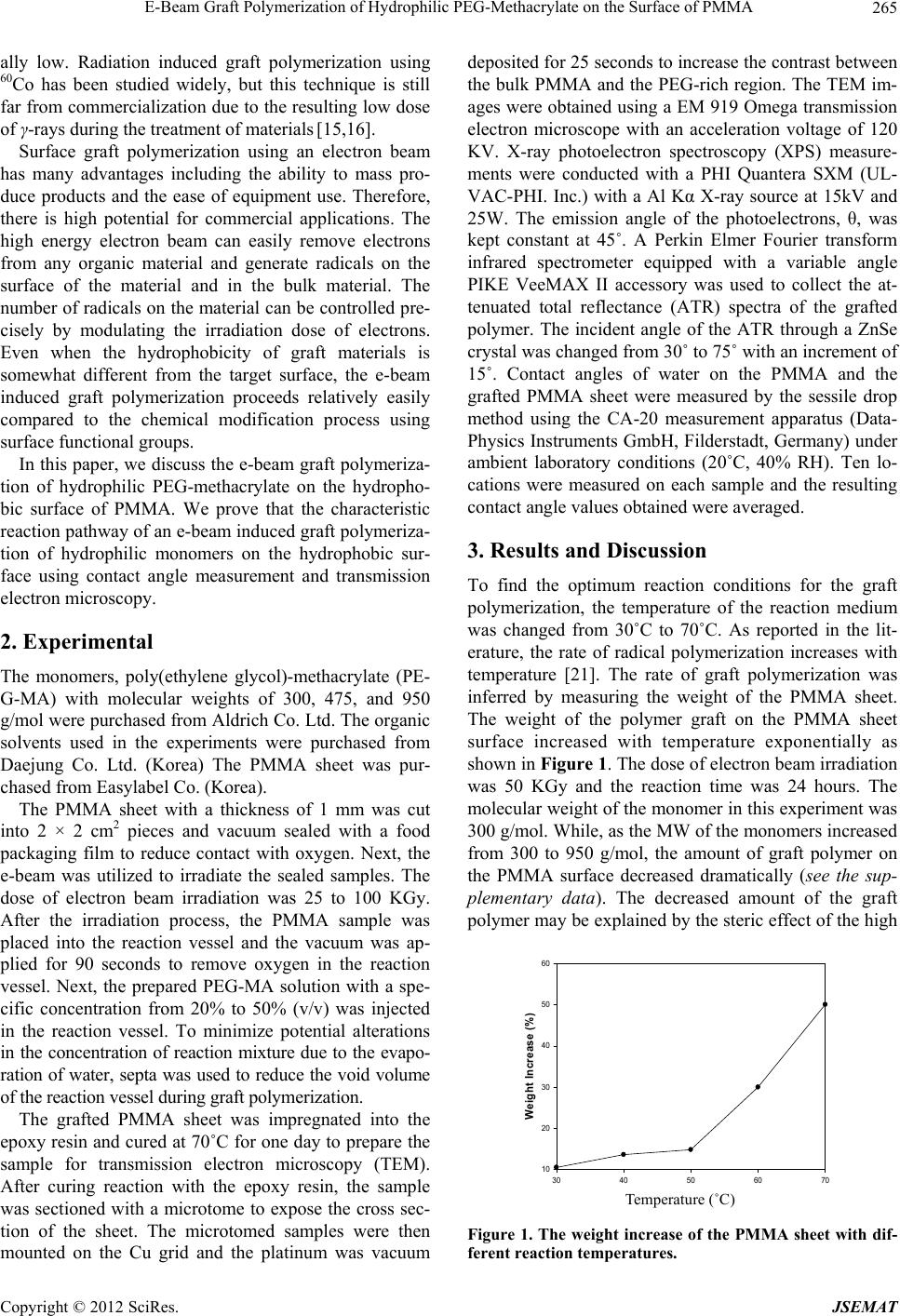 E-Beam Graft Polymerization of Hydrophilic PEG-Methacrylate on the Surface of PMMA 265 ally low. Radiation induced graft polymerization using 60Co has been studied widely, but this technique is still far from commercialization due to the resulting low dose of γ-rays during the treatment of materials [15,16]. Surface graft polymerization using an electron beam has many advantages including the ability to mass pro- duce products and the ease of equipment use. Therefore, there is high potential for commercial applications. The high energy electron beam can easily remove electrons from any organic material and generate radicals on the surface of the material and in the bulk material. The number of radicals on the material can be controlled pre- cisely by modulating the irradiation dose of electrons. Even when the hydrophobicity of graft materials is somewhat different from the target surface, the e-beam induced graft polymerization proceeds relatively easily compared to the chemical modification process using surface functional groups. In this paper, we discuss the e-beam graft polymeriza- tion of hydrophilic PEG-methacrylate on the hydropho- bic surface of PMMA. We prove that the characteristic reaction pathway of an e-beam induced graft polymeriza- tion of hydrophilic monomers on the hydrophobic sur- face using contact angle measurement and transmission electron microscopy. 2. Experimental The monomers, poly(ethylene glycol)-methacrylate (PE- G-MA) with molecular weights of 300, 475, and 950 g/mol were purchased from Aldrich Co. Ltd. The organic solvents used in the experiments were purchased from Daejung Co. Ltd. (Korea) The PMMA sheet was pur- chased from Easylabel Co. (Korea). The PMMA sheet with a thickness of 1 mm was cut into 2 × 2 cm2 pieces and vacuum sealed with a food packaging film to reduce contact with oxygen. Next, the e-beam was utilized to irradiate the sealed samples. The dose of electron beam irradiation was 25 to 100 KGy. After the irradiation process, the PMMA sample was placed into the reaction vessel and the vacuum was ap- plied for 90 seconds to remove oxygen in the reaction vessel. Next, the prepared PEG-MA solution with a spe- cific concentration from 20% to 50% (v/v) was injected in the reaction vessel. To minimize potential alterations in the concentration of reaction mixture due to the evapo- ration of water, septa was used to reduce the void volume of the reaction vessel during graft polymerization. The grafted PMMA sheet was impregnated into the epoxy resin and cured at 70˚C for one day to prepare the sample for transmission electron microscopy (TEM). After curing reaction with the epoxy resin, the sample was sectioned with a microtome to expose the cross sec- tion of the sheet. The microtomed samples were then mounted on the Cu grid and the platinum was vacuum deposited for 25 seconds to increase the contrast between the bulk PMMA and the PEG-rich region. The TEM im- ages were obtained using a EM 919 Omega transmission electron microscope with an acceleration voltage of 120 KV. X-ray photoelectron spectroscopy (XPS) measure- ments were conducted with a PHI Quantera SXM (UL- VAC-PHI. Inc.) with a Al Kα X-ray source at 15kV and 25W. The emission angle of the photoelectrons, θ, was kept constant at 45˚. A Perkin Elmer Fourier transform infrared spectrometer equipped with a variable angle PIKE VeeMAX II accessory was used to collect the at- tenuated total reflectance (ATR) spectra of the grafted polymer. The incident angle of the ATR through a ZnSe crystal was changed from 30˚ to 75˚ with an increment of 15˚. Contact angles of water on the PMMA and the grafted PMMA sheet were measured by the sessile drop method using the CA-20 measurement apparatus (Data- Physics Instruments GmbH, Filderstadt, Germany) under ambient laboratory conditions (20˚C, 40% RH). Ten lo- cations were measured on each sample and the resulting contact angle values obtained were averaged. 3. Results and Discussion To find the optimum reaction conditions for the graft polymerization, the temperature of the reaction medium was changed from 30˚C to 70˚C. As reported in the lit- erature, the rate of radical polymerization increases with temperature [21]. The rate of graft polymerization was inferred by measuring the weight of the PMMA sheet. The weight of the polymer graft on the PMMA sheet surface increased with temperature exponentially as shown in Figure 1. The dose of electron beam irradiation was 50 KGy and the reaction time was 24 hours. The molecular weight of the monomer in this experiment was 300 g/mol. While, as the MW of the monomers increased from 300 to 950 g/mol, the amount of graft polymer on the PMMA surface decreased dramatically (see the sup- plementary data). The decreased amount of the graft polymer may be explained by the steric effect of the high Temperature (oC) 30 40 50 60 70 Weight Increase (%) 10 20 30 40 50 60 Temperature (˚C) Figure 1. The weight increase of the PMMA sheet with dif- ferent rea c t i o n temperatures. Copyright © 2012 SciRes. JSEMAT 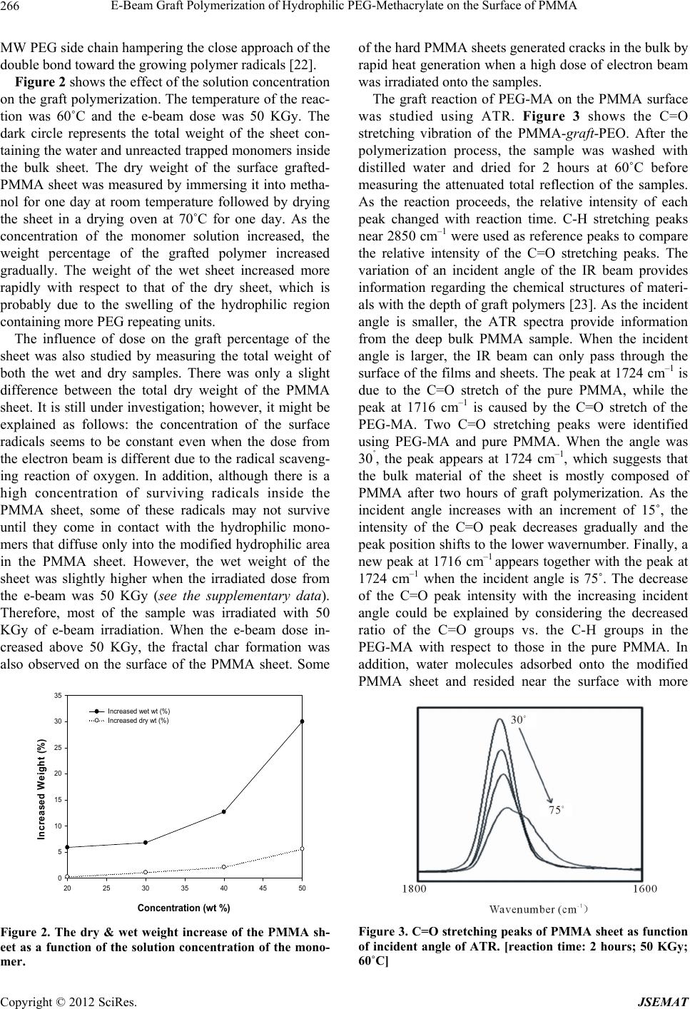 E-Beam Graft Polymerization of Hydrophilic PEG-Methacrylate on the Surface of PMMA 266 MW PEG side chain hampering the close approach of the double bond toward the growing polymer radicals [22]. Figure 2 shows the effect of the solution concentration on the graft polymerization. The temperature of the reac- tion was 60˚C and the e-beam dose was 50 KGy. The dark circle represents the total weight of the sheet con- taining the water and unreacted trapped monomers inside the bulk sheet. The dry weight of the surface grafted- PMMA sheet was measured by immersing it into metha- nol for one day at room temperature followed by drying the sheet in a drying oven at 70˚C for one day. As the concentration of the monomer solution increased, the weight percentage of the grafted polymer increased gradually. The weight of the wet sheet increased more rapidly with respect to that of the dry sheet, which is probably due to the swelling of the hydrophilic region containing more PEG repeating units. The influence of dose on the graft percentage of the sheet was also studied by measuring the total weight of both the wet and dry samples. There was only a slight difference between the total dry weight of the PMMA sheet. It is still under investigation; however, it might be explained as follows: the concentration of the surface radicals seems to be constant even when the dose from the electron beam is different due to the radical scaveng- ing reaction of oxygen. In addition, although there is a high concentration of surviving radicals inside the PMMA sheet, some of these radicals may not survive until they come in contact with the hydrophilic mono- mers that diffuse only into the modified hydrophilic area in the PMMA sheet. However, the wet weight of the sheet was slightly higher when the irradiated dose from the e-beam was 50 KGy (see the supplementary data). Therefore, most of the sample was irradiated with 50 KGy of e-beam irradiation. When the e-beam dose in- creased above 50 KGy, the fractal char formation was also observed on the surface of the PMMA sheet. Some Concentration (wt %) 20 25 30 35 40 45 50 Increased Weight (%) 0 5 10 15 20 25 30 35 Increased wet wt (%) Increased dry wt (%) Figure 2. The dry & wet weight increase of the PMMA sh- eet as a function of the solution concentration of the mono- mer. of the hard PMMA sheets generated cracks in the bulk by rapid heat generation when a high dose of electron beam was irradiated onto the samples. The graft reaction of PEG-MA on the PMMA surface was studied using ATR. Figure 3 shows the C=O stretching vibration of the PMMA-graft-PEO. After the polymerization process, the sample was washed with distilled water and dried for 2 hours at 60˚C before measuring the attenuated total reflection of the samples. As the reaction proceeds, the relative intensity of each peak changed with reaction time. C-H stretching peaks near 2850 cm–1 were used as reference peaks to compare the relative intensity of the C=O stretching peaks. The variation of an incident angle of the IR beam provides information regarding the chemical structures of materi- als with the depth of graft polymers [23]. As the incident angle is smaller, the ATR spectra provide information from the deep bulk PMMA sample. When the incident angle is larger, the IR beam can only pass through the surface of the films and sheets. The peak at 1724 cm–1 is due to the C=O stretch of the pure PMMA, while the peak at 1716 cm–1 is caused by the C=O stretch of the PEG-MA. Two C=O stretching peaks were identified using PEG-MA and pure PMMA. When the angle was 30˚, the peak appears at 1724 cm–1, which suggests that the bulk material of the sheet is mostly composed of PMMA after two hours of graft polymerization. As the incident angle increases with an increment of 15˚, the intensity of the C=O peak decreases gradually and the peak position shifts to the lower wavernumber. Finally, a new peak at 1716 cm–1 appears together with the peak at 1724 cm–1 when the incident angle is 75˚. The decrease of the C=O peak intensity with the increasing incident angle could be explained by considering the decreased ratio of the C=O groups vs. the C-H groups in the PEG-MA with respect to those in the pure PMMA. In addition, water molecules adsorbed onto the modified PMMA sheet and resided near the surface with more Figure 3. C=O stretching peaks of PMMA sheet as function of incident angle of ATR. [reaction time: 2 hours; 50 KGy; 60˚C] Copyright © 2012 SciRes. JSEMAT 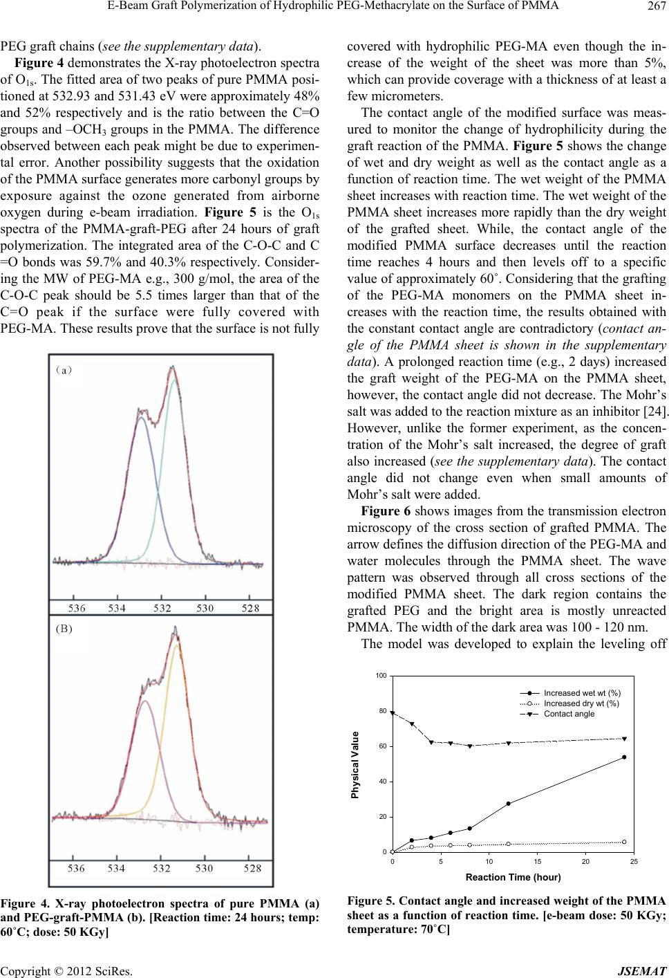 E-Beam Graft Polymerization of Hydrophilic PEG-Methacrylate on the Surface of PMMA 267 PEG graft chains (see the supplementary data). Figure 4 demonstrates the X-ray photoelectron spectra of O1s. The fitted area of two peaks of pure PMMA posi- tioned at 532.93 and 531.43 eV were approximately 48% and 52% respectively and is the ratio between the C=O groups and –OCH3 groups in the PMMA. The difference observed between each peak might be due to experimen- tal error. Another possibility suggests that the oxidation of the PMMA surface generates more carbonyl groups by exposure against the ozone generated from airborne oxygen during e-beam irradiation. Figure 5 is the O1s spectra of the PMMA-graft-PEG after 24 hours of graft polymerization. The integrated area of the C-O-C and C =O bonds was 59.7% and 40.3% respectively. Consider- ing the MW of PEG-MA e.g., 300 g/mol, the area of the C-O-C peak should be 5.5 times larger than that of the C=O peak if the surface were fully covered with PEG-MA. These results prove that the surface is not fully Figure 4. X-ray photoelectron spectra of pure PMMA (a) and PEG-graft-PMMA (b). [Reaction time: 24 hours; temp: 60˚C; dose: 50 KGy] covered with hydrophilic PEG-MA even though the in- crease of the weight of the sheet was more than 5%, which can provide coverage with a thickness of at least a few micrometers. The contact angle of the modified surface was meas- ured to monitor the change of hydrophilicity during the graft reaction of the PMMA. Figure 5 shows the change of wet and dry weight as well as the contact angle as a function of reaction time. The wet weight of the PMMA sheet increases with reaction time. The wet weight of the PMMA sheet increases more rapidly than the dry weight of the grafted sheet. While, the contact angle of the modified PMMA surface decreases until the reaction time reaches 4 hours and then levels off to a specific value of approximately 60˚. Considering that the grafting of the PEG-MA monomers on the PMMA sheet in- creases with the reaction time, the results obtained with the constant contact angle are contradictory (contact an- gle of the PMMA sheet is shown in the supplementary data). A prolonged reaction time (e.g., 2 days) increased the graft weight of the PEG-MA on the PMMA sheet, however, the contact angle did not decrease. The Mohr’s salt was added to the reaction mixture as an inhibitor [24]. However, unlike the former experiment, as the concen- tration of the Mohr’s salt increased, the degree of graft also increased (see the supplementary data). The contact angle did not change even when small amounts of Mohr’s salt were added. Figure 6 shows images from the transmission electron microscopy of the cross section of grafted PMMA. The arrow defines the diffusion direction of the PEG-MA and water molecules through the PMMA sheet. The wave pattern was observed through all cross sections of the modified PMMA sheet. The dark region contains the grafted PEG and the bright area is mostly unreacted PMMA. The width of the dark area was 100 - 120 nm. The model was developed to explain the leveling off Reaction Time (hour) 0510 15 20 25 Physical Value 0 20 40 60 80 100 Increased wet wt (%) Increased dry wt (%) Contact angle Figure 5. Contact angle and incr eased weight of the PMMA sheet as a function of reaction time. [e-beam dose: 50 KGy; temperature: 70˚C] Copyright © 2012 SciRes. JSEMAT 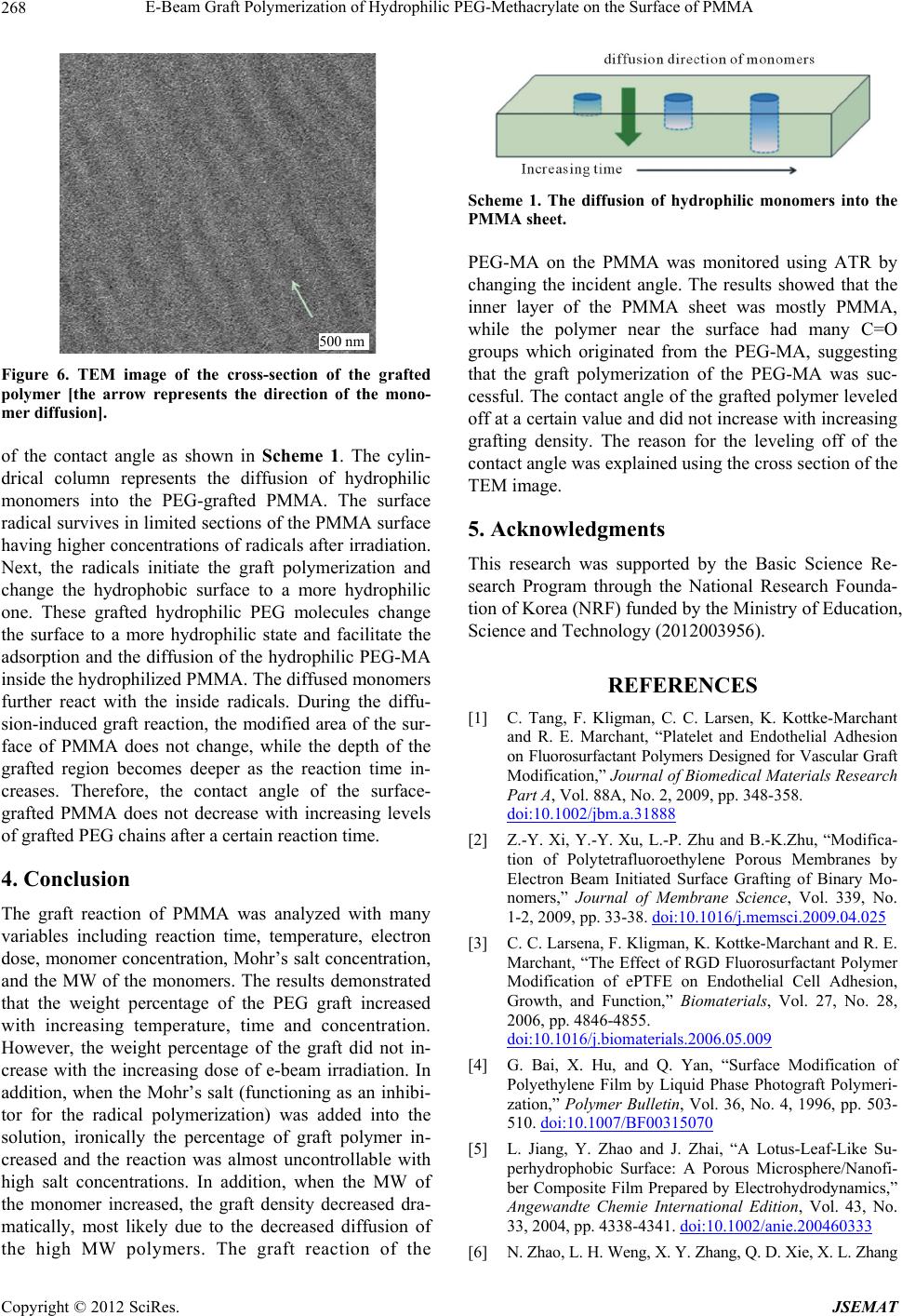 E-Beam Graft Polymerization of Hydrophilic PEG-Methacrylate on the Surface of PMMA 268 500 n m Figure 6. TEM image of the cross-section of the grafted polymer [the arrow represents the direction of the mono- mer diffusion]. of the contact angle as shown in Scheme 1. The cylin- drical column represents the diffusion of hydrophilic monomers into the PEG-grafted PMMA. The surface radical survives in limited sections of the PMMA surface having higher concentrations of radicals after irradiation. Next, the radicals initiate the graft polymerization and change the hydrophobic surface to a more hydrophilic one. These grafted hydrophilic PEG molecules change the surface to a more hydrophilic state and facilitate the adsorption and the diffusion of the hydrophilic PEG-MA inside the hydrophilized PMMA. The diffused monomers further react with the inside radicals. During the diffu- sion-induced graft reaction, the modified area of the sur- face of PMMA does not change, while the depth of the grafted region becomes deeper as the reaction time in- creases. Therefore, the contact angle of the surface- grafted PMMA does not decrease with increasing levels of grafted PEG chains after a certain reaction time. 4. Conclusion The graft reaction of PMMA was analyzed with many variables including reaction time, temperature, electron dose, monomer concentration, Mohr’s salt concentration, and the MW of the monomers. The results demonstrated that the weight percentage of the PEG graft increased with increasing temperature, time and concentration. However, the weight percentage of the graft did not in- crease with the increasing dose of e-beam irradiation. In addition, when the Mohr’s salt (functioning as an inhibi- tor for the radical polymerization) was added into the solution, ironically the percentage of graft polymer in- creased and the reaction was almost uncontrollable with high salt concentrations. In addition, when the MW of the monomer increased, the graft density decreased dra- matically, most likely due to the decreased diffusion of the high MW polymers. The graft reaction of the Scheme 1. The diffusion of hydrophilic monomers into the PMMA sheet. PEG-MA on the PMMA was monitored using ATR by changing the incident angle. The results showed that the inner layer of the PMMA sheet was mostly PMMA, while the polymer near the surface had many C=O groups which originated from the PEG-MA, suggesting that the graft polymerization of the PEG-MA was suc- cessful. The contact angle of the grafted polymer leveled off at a certain value and did not increase with increasing grafting density. The reason for the leveling off of the contact angle was explained using the cross section of the TEM image. 5. Acknowledgments This research was supported by the Basic Science Re- search Program through the National Research Founda- tion of Korea (NRF) funded by the Ministry of Education, Science and Technology (2012003956). REFERENCES [1] C. Tang, F. Kligman, C. C. Larsen, K. Kottke-Marchant and R. E. Marchant, “Platelet and Endothelial Adhesion on Fluorosurfactant Polymers Designed for Vascular Graft Modification,” Journal of Biomedical Materials Research Part A, Vol. 88A, No. 2, 2009, pp. 348-358. doi:10.1002/jbm.a.31888 [2] Z.-Y. Xi, Y.-Y. Xu, L.-P. Zhu and B.-K.Zhu, “Modifica- tion of Polytetrafluoroethylene Porous Membranes by Electron Beam Initiated Surface Grafting of Binary Mo- nomers,” Journal of Membrane Science, Vol. 339, No. 1-2, 2009, pp. 33-38. doi:10.1016/j.memsci.2009.04.025 [3] C. C. Larsena, F. Kligman, K. Kottke-Marchant and R. E. Marchant, “The Effect of RGD Fluorosurfactant Polymer Modification of ePTFE on Endothelial Cell Adhesion, Growth, and Function,” Biomaterials, Vol. 27, No. 28, 2006, pp. 4846-4855. doi:10.1016/j.biomaterials.2006.05.009 [4] G. Bai, X. Hu, and Q. Yan, “Surface Modification of Polyethylene Film by Liquid Phase Photograft Polymeri- zation,” Polymer Bulletin, Vol. 36, No. 4, 1996, pp. 503- 510. doi:10.1007/BF00315070 [5] L. Jiang, Y. Zhao and J. Zhai, “A Lotus-Leaf-Like Su- perhydrophobic Surface: A Porous Microsphere/Nanofi- ber Composite Film Prepared by Electrohydrodynamics,” Angewandte Chemie International Edition, Vol. 43, No. 33, 2004, pp. 4338-4341. doi:10.1002/anie.200460333 [6] N. Zhao, L. H. Weng, X. Y. Zhang, Q. D. Xie, X. L. Zhang Copyright © 2012 SciRes. JSEMAT 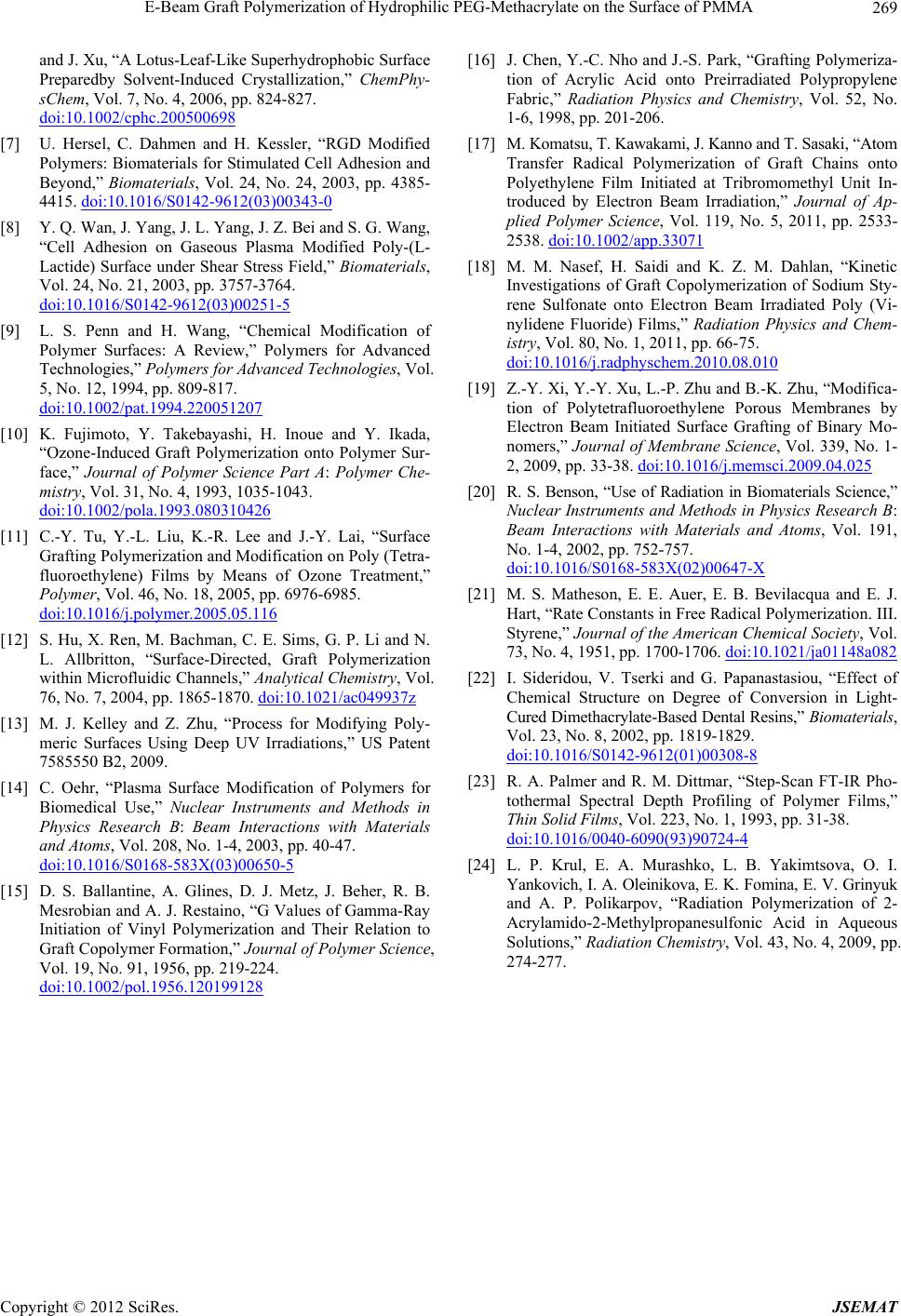 E-Beam Graft Polymerization of Hydrophilic PEG-Methacrylate on the Surface of PMMA Copyright © 2012 SciRes. JSEMAT 269 and J. Xu, “A Lotus-Leaf-Like Superhydrophobic Surface Preparedby Solvent-Induced Crystallization,” ChemPhy- sChem, Vol. 7, No. 4, 2006, pp. 824-827. doi:10.1002/cphc.200500698 [7] U. Hersel, C. Dahmen and H. Kessler, “RGD Modified Polymers: Biomaterials for Stimulated Cell Adhesion and Beyond,” Biomaterials, Vol. 24, No. 24, 2003, pp. 4385- 4415. doi:10.1016/S0142-9612(03)00343-0 [8] Y. Q. Wan, J. Yang, J. L. Yang, J. Z. Bei and S. G. Wang, “Cell Adhesion on Gaseous Plasma Modified Poly-(L- Lactide) Surface under Shear Stress Field,” Biomaterials, Vol. 24, No. 21, 2003, pp. 3757-3764. doi:10.1016/S0142-9612(03)00251-5 [9] L. S. Penn and H. Wang, “Chemical Modification of Polymer Surfaces: A Review,” Polymers for Advanced Technologies,” Polymers for Advanced Technologies, Vol. 5, No. 12, 1994, pp. 809-817. doi:10.1002/pat.1994.220051207 [10] K. Fujimoto, Y. Takebayashi, H. Inoue and Y. Ikada, “Ozone-Induced Graft Polymerization onto Polymer Sur- face,” Journal of Polymer Science Part A: Polymer Che- mistry, Vol. 31, No. 4, 1993, 1035-1043. doi:10.1002/pola.1993.080310426 [11] C.-Y. Tu, Y.-L. Liu, K.-R. Lee and J.-Y. Lai, “Surface Grafting Polymerization and Modification on Poly (Tetra- fluoroethylene) Films by Means of Ozone Treatment,” Polymer, Vol. 46, No. 18, 2005, pp. 6976-6985. doi:10.1016/j.polymer.2005.05.116 [12] S. Hu, X. Ren, M. Bachman, C. E. Sims, G. P. Li and N. L. Allbritton, “Surface-Directed, Graft Polymerization within Microfluidic Channels,” Analytical Chemistry, Vol. 76, No. 7, 2004, pp. 1865-1870. doi:10.1021/ac049937z [13] M. J. Kelley and Z. Zhu, “Process for Modifying Poly- meric Surfaces Using Deep UV Irradiations,” US Patent 7585550 B2, 2009. [14] C. Oehr, “Plasma Surface Modification of Polymers for Biomedical Use,” Nuclear Instruments and Methods in Physics Research B: Beam Interactions with Materials and Atoms, Vol. 208, No. 1-4, 2003, pp. 40-47. doi:10.1016/S0168-583X(03)00650-5 [15] D. S. Ballantine, A. Glines, D. J. Metz, J. Beher, R. B. Mesrobian and A. J. Restaino, “G Values of Gamma-Ray Initiation of Vinyl Polymerization and Their Relation to Graft Copolymer Formation,” Journal of Polymer Science, Vol. 19, No. 91, 1956, pp. 219-224. doi:10.1002/pol.1956.120199128 [16] J. Chen, Y.-C. Nho and J.-S. Park, “Grafting Polymeriza- tion of Acrylic Acid onto Preirradiated Polypropylene Fabric,” Radiation Physics and Chemistry, Vol. 52, No. 1-6, 1998, pp. 201-206. [17] M. Komatsu, T. Kawakami, J. Kanno and T. Sasaki, “Atom Transfer Radical Polymerization of Graft Chains onto Polyethylene Film Initiated at Tribromomethyl Unit In- troduced by Electron Beam Irradiation,” Journal of Ap- plied Polymer Science, Vol. 119, No. 5, 2011, pp. 2533- 2538. doi:10.1002/app.33071 [18] M. M. Nasef, H. Saidi and K. Z. M. Dahlan, “Kinetic Investigations of Graft Copolymerization of Sodium Sty- rene Sulfonate onto Electron Beam Irradiated Poly (Vi- nylidene Fluoride) Films,” Radiation Physics and Chem- istry, Vol. 80, No. 1, 2011, pp. 66-75. doi:10.1016/j.radphyschem.2010.08.010 [19] Z.-Y. Xi, Y.-Y. Xu, L.-P. Zhu and B.-K. Zhu, “Modifica- tion of Polytetrafluoroethylene Porous Membranes by Electron Beam Initiated Surface Grafting of Binary Mo- nomers,” Journal of Membrane Science, Vol. 339, No. 1- 2, 2009, pp. 33-38. doi:10.1016/j.memsci.2009.04.025 [20] R. S. Benson, “Use of Radiation in Biomaterials Science,” Nuclear Instruments and Methods in Physics Research B: Beam Interactions with Materials and Atoms, Vol. 191, No. 1-4, 2002, pp. 752-757. doi:10.1016/S0168-583X(02)00647-X [21] M. S. Matheson, E. E. Auer, E. B. Bevilacqua and E. J. Hart, “Rate Constants in Free Radical Polymerization. III. Styrene,” Journal of the American Chemical Society, Vol. 73, No. 4, 1951, pp. 1700-1706. doi:10.1021/ja01148a082 [22] I. Sideridou, V. Tserki and G. Papanastasiou, “Effect of Chemical Structure on Degree of Conversion in Light- Cured Dimethacrylate-Based Dental Resins,” Biomaterials, Vol. 23, No. 8, 2002, pp. 1819-1829. doi:10.1016/S0142-9612(01)00308-8 [23] R. A. Palmer and R. M. Dittmar, “Step-Scan FT-IR Pho- tothermal Spectral Depth Profiling of Polymer Films,” Thin Solid Films, Vol. 223, No. 1, 1993, pp. 31-38. doi:10.1016/0040-6090(93)90724-4 [24] L. P. Krul, E. A. Murashko, L. B. Yakimtsova, O. I. Yankovich, I. A. Oleinikova, E. K. Fomina, E. V. Grinyuk and A. P. Polikarpov, “Radiation Polymerization of 2- Acrylamido-2-Methylpropanesulfonic Acid in Aqueous Solutions,” Radiation Chemistry, Vol. 43, No. 4, 2009, pp. 274-277. 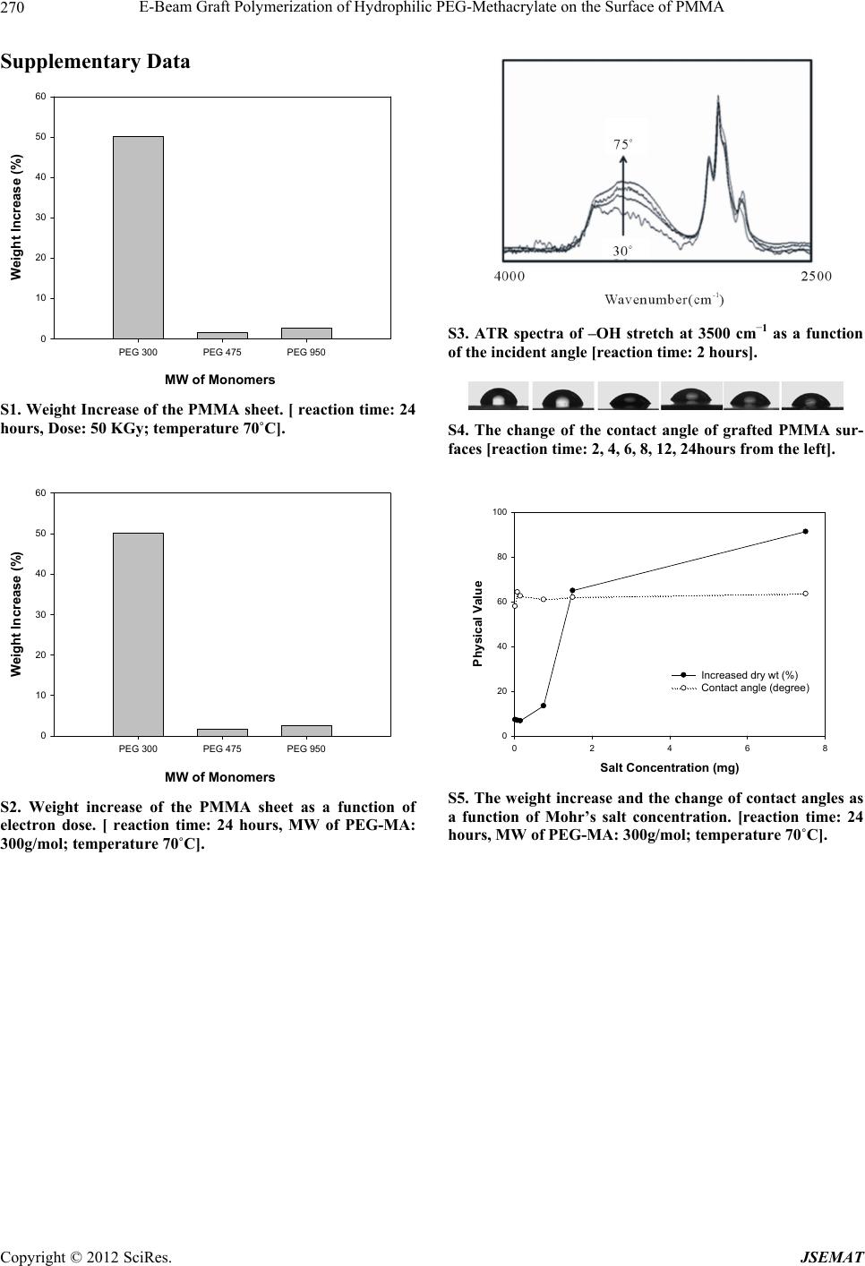 E-Beam Graft Polymerization of Hydrophilic PEG-Methacrylate on the Surface of PMMA 270 Supplementary Data MW of Monomers PEG 300PEG 475PEG 950 Weight Increase (%) 0 10 20 30 40 50 60 S1. Weight Increase of the PMMA sheet. [ reaction time: 24 hours, Dose: 50 KGy; temperature 70˚C]. MW of Monomers PEG 300PEG 475PEG 950 Weight Increase (%) 0 10 20 30 40 50 60 S2. Weight increase of the PMMA sheet as a function of electron dose. [ reaction time: 24 hours, MW of PEG-MA: 300g/mol; temperature 70˚C]. S3. ATR spectra of –OH stretch at 3500 cm–1 as a function of the incident angle [reaction time: 2 hours]. S4. The change of the contact angle of grafted PMMA sur- faces [reaction time: 2, 4, 6, 8, 12, 24hours from the left]. Salt Concentration (mg) 02468 Physical Value 0 20 40 60 80 100 Increased dry wt (%) Contact ang le (degree) S5. The weight increase and the change of contact angles as a function of Mohr’s salt concentration. [reaction time: 24 hours, MW of PEG-MA: 300g/mol; temperature 70˚C]. Copyright © 2012 SciRes. JSEMAT |