

Paper Menu >>
Journal Menu >>
 Intelligent Information Management, 2012, 4, 231-237 http://dx.doi.org/10.4236/iim.2012.45034 Published Online September 2012 (http://www.SciRP.org/journal/iim) A Critical Analysis and Treatment of Important UML Diagrams Enhancing Modeling Power Fahad Alhumaidan College of Computer Sciences and IT, King Faisal University, Hofuf, KSA Email: falhumai[email protected] Received May 10, 2012; revised June 13, 2012; accepted July 1, 2012 ABSTRACT Requirements analysis and design specification are serious issues in systems development because of the semantics in- volved in transformation of real world problems to computer software systems. Although unified modeling language (UML) is now accepted as a de facto standard for design and specification of object oriented systems but its structures have various disadvantages. For example, it lacks of defining semantics of the systems to be developed. Formal meth- ods are proved powerful, particularly, at requirement specification and design level. To address and realize the benefits of UML and formal methods our project on “formalization of UML diagrams using Z notation” is under progress. This paper is continuation of the same project in which some important diagrams namely use case, class and sequence dia- grams are selected for critical analysis. Merits and demerits of the diagrams are addressed after a brief introduction. Applications of the diagrams are observed reducing complexity and proposing a good design of a system. Finally, a treatment to link diagrams with appropriate appro ach es is sugg ested to enhan ce modeling power of UML for facilitating the systems development. Keywords: UML; Critical Analysis; Use Cases; Sequence Diagrams; Class Diagrams 1. Introduction Requirements analysis and design specification in soft- ware engineering are challenging tasks because trans- formation of real world problems into verifiable com- puter models has made it a hard issue [1]. The emergence of the Unified Modeling Language (UML) has raised some interesting issues because it has incorporated a number of object oriented analysis and design techniques into a single modeling language. Because of an obvious usage and tool support of UML modeling techniques, it plays an important role in design and implementation phases in the construction of software systems. However some weaknesses existing in UML notations have invited software engineers to find other approaches considering compatibil ity and integratio n i s s u e s w it h U M L mo d e l s for the complete and consistent, modeling, design and deve- lopment [2]. The UML is a collection of diagrams for specifying various aspects such as requirements and design of soft- ware systems. It is a standard set of notations for visual- izing and constructing artifacts of software systems as well as for business modeling and other non-software systems [3]. UML has become a de facto standard for de- sign and development of object oriented (OO) systems despite the fact that its semantics is semi-formal which allows ambiguities in design of a system [4]. Some of th e issues in modeling using UML, being hybrid and visual language in nature, are summarized below: As most of the UML structures are based on graphical notations and hence are prone to causing errors; The hidden semantics under the UML diagrams allow ambiguities at design level of computer software sys- tems; We know the same system can be described and mo- deled by multiple UML notations producing an in- consistent or ambiguous model; Any model described using UML diagrams may have multiple interpretations and, hence, the recipients of the design may not be able to really understand what has been put in the diagra ms. Much of the UML structures are based on graphical notations having informal or semi-formal definitions which are prone to cause errors [2] as mentioned above. Modeling power of UML can be enhanced by linking it with formal methods and defining semantic rules in a formal way for the diagrams used in design of a system [5]. There is a need of linking and formalizing UML dia- grams to other useful approaches to get full benefit at design level capturing complete functionality of the sys- tem to be developed. This is one of the objectives of this research. This work is part of our ongoing project on integration of UML and Z notation [6]. The integration C opyright © 2012 SciRes. IIM  F. ALHUMAIDAN 232 of formal notations and UML diagrams will result an ap- proach for complete, consistent and correct modeling of complex systems. There exists a few work formalizing UML and formal methods presented in the next section in which mostly it is focused on syntax of the diagrams. In our project, in- stead of defining only syntactical mapping between UML and Z we have focused to propose and develop a con- ceptual model by capturing its semantics hidden under the diagrams. In this paper, in continuation to our pre- vious work, three important diagrams namely use cases, class diagrams and sequence diagrams are considered. An introduction to each diagram is presented. Then ad- vantages, applications and role of diagrams in software engineering are discussed. The weaknesses of the dia- grams are identified. Finally, a treatment is suggested to link UML with other appropriate approaches. The major objectives of this research are: Identifying weakness existing in UML and hidden semantics under the diagrams; Listing benefits of formal techniques for software en- gineering, particularly, at requirements analysis and design specification of systems; Proposing an integration of UML and formal appro- aches to be useful in modeling of complex software systems; Investigating and providing syntactical and seman- tics-based relationships between most commonly used UML diagrams and Z notation; Analyzing and proving correctness of the proposed models of integration; Finally, developing an approach to provide an autom- ated tool support to transform UML models to Z spe- cification. Rest of the paper is organized as follows: in Section 2, related work is discussed. A critical analysis, significance and limitations of the UML diagrams are provided in Sections 3 and 4. Proposed treatment is suggested in Sec- tion 5. Finally, conclusion and future work are discussed in Section 6. 2. Related Work Although there exits a lot of work [7-11] on integration of approaches but there does not exists much work on linking UML diagrams with formal approaches. This is because the hidden semantics under the UML diagrams cannot be transformed easily into formal notations. It is mentioned that only closely related work is discussed in this section. For example, [12] has developed Alloy Con- straint Analyzer tool supporting the description of a sys- tem whose state space involves relational structures which are complex in nature. By the tool it is possible to analyze and develop a model by investigating the cons- equences of given constraints by an incremental app- roach. An approach is demonstrated using XML which is in fact a transformation tool to analyze visualize Timed Communicating Object Z (TCOZ) models into various UML diagrams animating specification with a multipar- adigm programming language as discussed in [13]. It is described a way of creating tables and SQL code for Z specifications according to UML diagrams in [14]. A case study is discussed by a formal verification method for Cooperative Composition Modeling Language (CCML) in [15]. In [16], semantic translation from statechart dia- grams to Object-Z specifications is presented. Informa- tion is captured using sequence and use case diagrams as a functional model by taking a case study. In another work, a relationship is investigated between Petri-nets and Z notation in [17]. A method for transla- ting and verifying UML sequence diagrams to Petri nets for deadlock, safety and liveness properties by model checking is presented in [18]. An integration of B and UML is presented in [19]. It is investigated the reliability issues using fuzzy logic and petri-nets in [20]. The mathe- matical induction technique is used to prove correctness of recursive programs in [21]. Formalization of the UML is proposed by focusing on basic constructs of class structures by taking simple case studies in [22]. A tool is developed in [1] which takes UML class diagram in the form of petal files, ASCII format files generated by Ra- tional Rose, and evaluates it automatically and produces a list of comments. Activity model is proposed by ontol- ogy based formal method in [23]. In [24], a mathematical extension to the OCL language is presented to manipu- late some mathematical concepts including fu nctions and relations. A comparison of UML, state-charts, Z notation, petri nets and fuzzy logic is presented by taking a simple case study on commerce system as discussed in [25]. Some other relevant work is listed in [26-30]. 3. An Overview of UML An introduction and critical analysis to UML diagrams and notations is presented in this section. Merits and de- merits of UML are listed. The reasoning of linking and formalizing UML is provided. UML has various benefits for modeling of complex systems. For example, UML is a semi-formal language in which each element of the language is strongly defined [31]. That is you are confident when modeling a particu- lar facet of a system in a sense that it will not mislead to an incorrect design. UML is a concise and easy to under- stand designing language [32]. The entire language is made up of simple and straightforward concepts and no- tations. It is comprehensive language and describes all important aspect of a system. Although UML is not a for- mal language but it has enough exp ressive power to han- dle massive and complex systems [33]. It is the result of best practices in modeling of complex systems using ob- Copyright © 2012 SciRes. IIM  F. ALHUMAIDAN 233 ject-oriented concepts and has proved to be a successful modeling practice. UML has become a de facto stan- dard for modeling of systems using object oriented tech- nology [34]. Further discussion about UML analysis can be found in [35-41]. Despite the above benefits, UML lacks with some im- portant concepts and for a moment cannot be used for the complete and consistent design and specification of a system [2]. For example, UML lacks formal semantics. Meanings are hidden under diagrams which create am- biguities at the implementations level. That is why inte- gration of UML with other appropriate approaches is required for the complete and consistent modeling. 4. Critical Analysis of Some Diagrams First of all, an introduction to each diagram is given then its benefits and limitations are analyzed. Finally impro- vements are suggested to enhance or link it with other modeling approaches. A critical analysis of the following diagrams is presented in this section. 4.1. Use Case Diagram Use case diagram is one of the UML diagrams that is used to represent th e fun ctio nality of th e syste m. It shows the functionality that the system will provide and the users who will communicate with the system to use that functionality [42]. The use case was dev eloped by Jacob- son et al. [43]. The use case diagram includes the nota- tions such as actors, use cases, communication associa- tion and the system or subsystem boundary. The use case diagrams provide interactions between roles known as actors and system to achieve a certain goal. Human or external system both are assumed as actors in definition of use case diagrams. Use cases define function nality of the system from a users’ perspective and are used to do- cument the system scope. Usually, use cases are used at a higher level in systems engineering as compared to their use in software engineering. A critical analysis of using use cases is presented after an introduction given below. 4.1.1. Benefits The role of use cases is required and observed at the analysis phase of modeling and system designing and it provides obvious benefits at this part of modeling the systems. As we know complexity is one of the major iss- ues in systems analysis and design. An important benefit of using use cases is that it helps managing complexity of systems. This is because it emphases on specific usage by starting from a very simple viewpoint by focusing on the users of the systems. The use cases provide a basic framework from requirements analysis to test cases gen- eration which is another important benefit of it. Further, use cases facilitate to designers to specify and achieve the final goals in the system development. 4.1.2. Weakne sses Despite the benefits of use cases there are some draw- backs for model ing systems using use cases. For e xample, motivations and experience of users are not considered in use cases. The usefulness and usability are important variables in software engineering which are not consid- ered. There is no systematic and well-organized mecha- nism to address the non-functional requirements in use case diagram. On the other side the non-functional re- quirements are important in quality issues and play a crucial role to the success of a software syste m . Use cases consider requirements separately and there is no proce- dure to define interaction between the requirements. Also The use case diagram notations are not enough to de- scribe the system functionality but it is supported with use case description which is a brief or detailed one. Time is another issue for using use cases because prepa- ration of the whole system requires much time using such diagrams however it depends on the size of the system. Finally use cas es are considered very ambiguous which do not capture ful ly the system. As a conseque nce developing automated computer tools which can transform use cases to other diagrams, for example class and sequence dia- grams, is a c hallenge in system s and software engi neering. 4.1.3. Improvement To capture the syntax and semanti cs of use case dia grams, it is suggested to transform the diagrams by semi-auto- mated way. In this way, the actor-actor and actor-system and system -system relat ionshi ps ca n be descr ibed to i den - tify the statics and dynamics of the system. 4.2. Class Diagram Class diagram is a structure diagram that is used to show the classes and their association with each other. The class diagram includes the notations such as classes, at- tributes, operations and associations [42]. Classes in UML diagrams are used to capture the information about the system to be developed. A class is an artifact in UML diagrams which can create any number of objects that share the attributes, operations, relationships among the objects, and some other semantics in the diagrams. Ab- stract classes cannot have objects and are useful to define a common interface. However, a subclass of an abstract class can have instances. A class in UML consists of three compartments which contain class name, attributes and operations. 4.2.1. Benefits Classes in UML are the most important building blocks for object oriented systems modeling and design. Attri- butes visibility in class diagrams can be public, package, Copyright © 2012 SciRes. IIM  F. ALHUMAIDAN 234 protected or private which is an excellent modeling prac- tice because in this way protecting security of data is guaranteed if required. Multiplicity in the relationships among class diagrams is an important concept which is required in many appli- cations, for example, from family relations to relational databases. Four main kinds of relationships, namely, as- sociation, generalization, aggregation and composition exist among classes. Association relationship is used in order to capture the relations among the objects of the classes. In this relationship it is specified how objects are connected to each other. A relation is a link relating one set to another with information needed to be related. There are various kind of association relationships, namely, many to many, many to one, one to many and one to one. For example in class-teacher relationship, as one teacher can teach many classes and one class can be taught by many teachers that is why we can describe this relation as many to many. In another example of student super- visor, if we suppose that one student can be supervised by only one supervisor and one supervisor can supervise many students it will be a many to one relationship. If we change student-supervisor to supervisor-student it will become one to many relationship. If we take an example of a society where a man can marry to one women and vice-versa, it will be the case of one to on e relationship. 4.2.2. Weakne sses Although relationships among class diagrams are impor- tant but it is difficult to implement specially for generat- ing class diagrams to specification for the next phase. In case of multiplicity relationship, if an intersection of two objects exists and a new object is introduced then the multiplicity rel ationship will be ch anged by ch anging de- sign of the system. Class diagrams are generally used to catch the static aspects of a system and their use is com- mon in software development. However, sometimes it is required for designers to analyze static as well as dy- namic of the system. 4.2.3. Improvement The relationships in class diagrams play a fundamental key role in the design of a system. Further, some impor- tant relationships do not exist in the diagrams. For exam- ple, symmetry, asymmetry, transitivity and equivalence are relations which are very much needed in modeling of any type of a system but these relations are not directly defined in the class diagrams. Such kind of relationships must be specified to enrich the UML class diagrams. As we know many to many, many to one, one to many and one to one relationships are usually represented by * ···*, * ··· 1, 1 ··· * and 1 ··· 1 notations respectively which do not provide a sufficient information in the semantics of the diagrams. If we extend the class diagrams by the propositional and predicate logic at such places, it will provide a good treatment for the UML class diagrams. 4.3. Sequence Diagram Sequence diagram is an interaction (behavior) diagram that shows the interaction between objects that are ar- ranged in a time sequence [42]. An introductio n, benefits, weaknesses and suggested improvements of the sequence diagrams are discussed in the following subsections. It shows the interaction between objects in which they are modeled by their roles and communicate by mes- sage passing; The sequence diagram includes notations such as the diagram name and frame, objects (lifelines), messages, activation and time axis. Sequence diagrams capture and model messages with- in the system for both analysis and design purposes in dynamic modeling by focusing on identification of be- havior. In particular, sequence diagram represents the flow of events, messages and interactions between the objects of a system in two dimensions. Objects interaction and time make the two dimensional model in the dia- grams. Objects interaction is displayed in horizontal line and time is represented in the vertical line of the diagram. It is a good modeling and designing tool because it pro- vides a dynamic view of system showing behavior which is not possible to extract from statics of the system. These diagrams are useful for modeling complex inter- actions between components and are, particularly, requ- ired for representing parallelism o f interaction . The UML sequence diagrams are used to refine the details under use cases. When use cases are combined with the corre- sponding sequence diagrams the ex pect ed b e havior of the system can easily be visualized. 4.3.1. Benefits The sequence diagrams help to discover architectural view and understand logic statement of the system at early stages in the design process. After having a separate set of sequence diagrams, the timing option gives us consis- tent implementation by integrating the diagrams. The se- quence diagrams are valuable because it helps the de- signers to reason about details of a system. For example, objects, object states, object interaction, sequence order, responsibilities, functionalities and timings issues can be easily addressed. The analysis using sequence diagrams serves as a good starting point for the design. Further, it is easy to enhance or modify the system after the new requirements have added. Sequence diagrams also facili- tate the documentation at various levels of abstraction which is usually not easy when it is required to create from the static part of the system. Copyright © 2012 SciRes. IIM 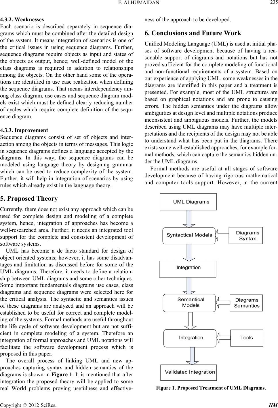 F. ALHUMAIDAN 235 4.3.2. Weakne sses Each scenario is described separately in sequence dia- grams which must be combined after the detailed design of the system. It means integration of scenarios is one of the critical issues in using sequence diagrams. Further, sequence diagrams require objects as input and states of the objects as output, hence; well-defined model of the class diagrams is required in addition to relationships among the objects. On the other hand some of the opera- tions are identified in use case realization when defining the sequence diagrams. That means interdependency am- ong class diagram, use cases and sequence diagram mod- els exist which must be defined clearly reducing number of cycles which require complete definition of the sequ- ence diagram. 4.3.3. Improvement Sequence diagrams consist of set of objects and inter- action among the objects in terms of messages. This logic in sequence diagrams defines a language accepted by the diagrams. In this way, the sequence diagrams can be modeled using language theory by designing grammar which can be used to reduce complexity of the system. Further, it will help in integration of scenarios by using rules which already exist in the language theory. 5. Proposed Theory Currently, there does not exist any ap proach whic h ca n be used for complete design and modeling of a complete system, hence, integration of approaches has become a well-researched area. Further, it needs an integrated tool support for the complete and consistent development of software systems. UML has become a de facto standard for design of object oriented systems; however, it has some disadvan- tages and limitation as discussed before for some of the UML diagrams. Therefore, it needs to define a relation- ship between UML diagrams and some other techniques. Some important fundamentals diagrams use cases, class diagrams and sequence diagrams were selected here for the critical analysis. The syntactic and semantics issues of these diagrams are analyzed and an approach will be established to be useful for correct and complete model- ing of the systems. Formal methods are useful throughout the life cycle of software development but are not suffi- cient in complete modeling of a system. Therefore an integration of formal appro aches and UML notation s will facilitate the software development process which is proposed in this paper. The overall process of linking UML and new ap- proaches capturing syntax and hidden semantics of the diagrams is shown in Figure 1. It is mentioned that after integration the proposed theory will be applied to some real World problems proving usefulness and effective- ness of the approach to be developed. 6. Conclusions and Future Work Unified Modeling Language (UML) is used at initial pha- ses of software development because of having a rea- sonable support of diagrams and notations but has not proved sufficient for the comp lete modeling of function al and non-functional requirements of a system. Based on our experie nce of ap plyi ng UML, s om e weaknesses i n the diagrams are identified in this paper and a treatment is presented. For example, most of the UML structures are based on graphical notations and are prone to causing errors. The hidden semantics under the diagrams allow ambiguities at design level and multiple notations produce inconsistent and ambiguous models. Further, the models described using UML diagrams may have multiple inter- pretations and t he recipients of t he design m ay not be a ble to understand what has been put in the diagrams. There exists some well-established approaches, for example for- mal methods , which ca n capture the semantics hidde n u n - der the UML diagrams. Formal methods are useful at all stages of software development because of having rigorous mathematical and computer tools support. However, at the current Figure 1. Proposed Treatment of UML Diagrams. Copyright © 2012 SciRes. IIM  F. ALHUMAIDAN 236 stage of developm ent, formal methods a re not sufficient i n complete modeling of a system. In this way, UML and formal methods are both useful for design and specific- ation of software systems but an integration of these approaches will facilitate the software development proc- ess which is proposed in this paper. Based on the identification of limitations, weaknesses and critical analysis of UML diagrams, an integrated approach will be proposed and developed for modeling of complex systems in our future work. 7. Acknowledgements I would like to thank Deanship of Scientific Research, King Faisal University (KFU), providing funds for con- ducting this research. I would like to acknowledge the Software Engineering Research Group at College of Co- mputer Sciences and Information Technology, KFU, for their valuable comments to improve quality of the rese- arch. REFERENCES [1] N. H. Ali, Z. Shukur and S. Idris, “A Design of an As- sessment System for UML Cla ss Diagram,” International Conference on Computational Science and Applications, Kuala Lampur, 26-29 August 2007, pp. 539-546. doi:10.1109/ICCSA.2007. 31 [2] A. M. Mostafa, A. I. Mana l, E. B. Hatem and E. M. Saa d, “Toward a Formalization of UML2.0 Meta-Model Using Z Specifications,” Proceedings of 8th ACIS International Conference on Software Engineering, Artificial Intelli- gence, Networking and Parallel/Distributed Computing, Qingdao, 30 July-1 August 2007, pp. 694-701. doi:10.1109/SNPD. 2007.508 [3] K. E. Hamdy, M. A. Elsoud and A. M. El-Halawany, “UML-Web Engineering Framework for Modeling Web Application,” Journal of Software Engineering, Vol. 5, No. 2, 2011, pp. 49-63. doi:10.3923/jse.2011.49.63 [4] X. He, “Formalizing UML Class Diagrams: A Hierarchi- cal Predicate Transition Net Approach,” Proceedings of Twenty-Fourth Annual International Computer Software and Applications Conference, Taipei, 25-27 October 2000, pp. 217-222. doi:10.1109/CMPSAC.2000. 884721 [5] M. Shroff and R. B. France, “Towards Formalization of UML Class Structures in Z,” 21st International Confe- rence on Computer Software and Applications, Washing- ton DC, 11-15 August 1997, pp. 646-651. [6] N. A. Zafar and F. Alhumaidan, “Transformation of Class Diagrams into Formal Specification,” International Jour- nal Computer Science and Network Security, Vol. 11, No. 5, 2011, pp. 289-295. [7] B. Akbarpour, S. Tahar and A. Dekdouk, “Formalization of Cadence SPW Fixed-Point Arithmetic in HOL,” For- mal Methods in System Design, Vol. 27, 2005, pp. 173- 200. [8] H. Beek, A. Fantechi, S. Gnesi and F. Mazzanti, “State/ Event-Based Software Model Checking,” Proceedings of 4th International Conference on Integrated Formal Meth- ods, Canterbury, 4-7 April 2004, pp. 128-147. [9] J. Derrick and G. Smith, “Structural Refine ment of Object- Z/CSP Specification,” Proceedings of 2nd International Conference on Integrated Formal Methods, Dagstuhl Castle, 1-3 November 2000, pp. 194-213. [10] O. Hasan and S. Tahar, “Verification of Probabilistic Pro- perties in the HOL Theorem Prover,” Proceedings of the 6th International Conference of Integrated Formal Meth- ods, Oxford, 2-5 July 2007, pp. 333-352. [11] T. B. Raymond, “Integrating Formal Methods by Uni- fying Abstractions,” Springer, Berlin, 2004, pp. 441-460. [12] D. Jackson, I. Schechter and I. Shlyakhter, “Alcoa: The Alloy Constraint Analyzer,” Proceedings of International Conference on Software Engineering, Limerick, 4-11 June 2000, pp. 730-733. doi:10.1109/ICSE. 2000.870482 [13] J. Sun, J. S. Dong, J. Liu and H. Wang, “A XML/XSL Approach to Visualize and Animate TCOZ,” Proceedings of 8th Asia-Pacific Software Engineering Conference, Macao, 4-7 December 2001, pp. 453-460. doi:10.1109/APSEC.2001.991514 [14] A. Moeini and R. O. Mesbah, “Specification and Develop- ment of Database Applications Based on Z and SQL,” Proceedings of International Conference on Information Management and Engineering, Kuala Lumpur, 3-5 April 2009, pp. 399-405. doi:10.1109/ICIME.2009.143 [15] X. G. Zhang and H. Liu, “Formal Verification for CCML Based Web Service Composition,” Information Techno- logy Journal, Vol. 10, No. 9, 2011, pp. 1692-1700. doi:10.3923/ itj.2011.1692.1700 [16] S.-K. Kim and D. Carrington, “An Integrated Framework with UML and Object-Z for Developing a Precise and Understandable Specification: The Light Control Case Study,” Proceedings of 7th Asia-Pacific Software Engi- neering Conference (APSEC), 5-8 December 2000, pp. 240-248. doi:10.1109/APSEC.2000.896705 [17] M. Heiner, and M. Heisel, “Modeling Safety Critical Sys- tems with Z and Petri-Nets,” Proceedings of International Conference on Computer Safety, Reliability and Security, Toulouse, 27-29 September 1999, pp. 361-374. [18] E. Cunha, M. Custodio, H. Rocha and R. Barreto, “For- mal Verification of UML Sequence Diagrams in the Em- bedded Systems Context,” Brazilian Symposium on Com- puting System Engineering (SBESC), 2011, pp. 39-45. [19] H. Leading and J. Souquieres, “Integration of UML and B Specification Techniques: Sy stematic Transformation from OCL Expressions into B,” Proceedings of 9th Asia-Pa- cific Software Engineering Conference, Gold Coast, 4-6 December 2002, p. 495. [20] Z. Shi, “Intelligent Target Fusion Recognition Based on Fuzzy Petri Nets,” Information Technology Journal, Vol. 11, No. 4, 2012, pp. 500-503. doi:10.3923/itj.2012.500.503 [21] C. Yong, “Application of Wu’s Method to Proving Total Correctness of Recursive Program,” Information Techn- ology Journal, Vol. 9, No. 7, 2010, pp. 1431-1439. doi:10.3923/ itj.2010.1431.1439 Copyright © 2012 SciRes. IIM  F. ALHUMAIDAN Copyright © 2012 SciRes. IIM 237 [22] Z. M. Ma, “Fuzzy Conceptual Information Modeling in UML Data Model,” International Symposium on Com- puter Science and Computational Technology, Shanghai, 20-22 December 2008, pp. 331-334. doi:10.1109/ ISCSCT.2008.353 [23] Z. X. Wang, H. He, L. Chen and Y. Zhang, “Ontology Based Semantics Checking for UML Activity Model,” Information Technology Journal, Vol. 11, No. 3, 2012, pp. 301-306. doi:10.3923/itj. 2012.301.306 [24] M. T. Bhiri, K. Mourad, M. Graiet and P. Aniorte, “UML/ OCL and Refinement,” 18th IEEE International Confe- rence and Workshops on Engineering of Computer-Based Systems, Las Vegas, 27-29 April 2011, pp. 14-158. [25] S. A. Ehikioya and B. Ola, “A Comparison of Formalisms for Electronic Commerce Systems,” Proceedings of Inter- national Confere nce on Comp utat ional Cybe rnetic s, Vienna, 30 A ug us t -1 S e pt e mbe r 2004, pp. 253-258. doi:10.1109/ICCCYB. 2004.1437721 [26] W. S. Changchien, J. J. Shen and T. Y. Lin, “A Prelimi- nary Correctness Evaluation Model of Object-Oriented Software Based on UML,” Journal of Applied Sciences, Vol. 2, No. 3, 2002, pp. 356-365. doi:10.3923/jas.2002.356.365. [27] Z. Derakhshandeh, B. T. Ladani and N. Nematbakhsh, “Modeling and Combining Access Control Policies Using Constrained Policy Graph (CPG),” Journal of Applied Sciences, Vol. 8, No. 20, 2008, pp. 3561-3571. doi:10.3923/jas.2008.3561.3571 [28] C. Liu and X. M. Dong, “An Improved Quasi-Static Scheduling Algorithm for Mixed Data-Control Embedded Software,” Journal of Applied Sciences, Vol. 6, No. 7, 2006, pp. 1571-1575. [29] S. Sengupta and S. Bhattacharya, “Formalization of UML Diagrams and Consistency Verification: A Z Notation Based Approach,” Proceedings of India Software Engi- neering Conference, Hyderabad, 19-22 February 2008, pp. 151-152. doi:10.1145/ 1342211.1342248 [30] X. Than, H. Miao and L. Liu, “Formalizing Semantics of UML Statecharts with Z,” Proceedings of 4th Internatio- nal Conference on Computer & Information Technology, Wuhan, 14-16 September 2004, pp. 1116-1121. doi:10.1109/ CIT.2004.1357344 [31] R. Borges and A. Mota, “Integrating UML and Formal Methods,” Electronic Notes in Theoretical Computer Sci- ence, Vol. 184, 2003, pp. 97-112. doi:10.1016/j.entcs.2007.03.017 [32] H. Podeswa, “UML for IT Business Analyst,” 2nd Edi- tion, Course Technology, 2009. [33] A. Dennis, B. H. Wixo m and D. Tegarden, “Systems Ana- lysis and Design with UML,” 3rd Edition, Wiley, Ho- boken, 2005. [34] R. Miles, and K. Hamilton, “Learning UML 2.0,” O’Reil- ly Media, 2006. [35] S. Zarina, N. Alias, M. M. Halip and B. Idrus, “Formal Specification and Validation of Selective Acknowledge- ment Protocol Using Z/EVES Theorem Prover,” Journal of Applied Sciences, Vol. 6, No. 8, 2006, pp. 1712-1719. doi:10.3923/jas.2006.1712.1719 [36] J. M. Wing, “A Specifier, Introduction to Formal Me- thods,” Computer Journal, Vol. 23, No. 9, 1990, pp. 8-24. doi:0.1109/2.58215. [37] F. Gervais, M. Frappier and R. Laleau, “Synthesizing B Specifications from EB3 Attribute Definitions,” Proceed- ings of 5th International Conference on Integrated For- mal Methods, Eindhoven, 29 November-2 December 2005, pp. 207-226. [38] A. Hall, “Correctness by Construction: Integrating For- mality into a Commercial Development Process,” Pro- ceedings of International Symposium of Formal Methods Europe, Copenhagen, 22-24 July 2002, pp. 139-157. [39] M. Brendan and J. S. Dong, “Blending Object-Z and Ti- med CSP: An Introduction to TCOZ,” Proceedings of In- ternational Conference on Software Engineering, Kyoto, 19-25 April 1998, pp. 95-104. doi:10.1109/ICSE.1998.671106. [40] M. Bo, W. Huang and J. Qin, “Automatic Verification of Security Properties of Remote Internet Voting Protocol in Symbolic Model,” Information Technology Journal, Vol. 9, No. 8, 2010, pp. 1521-1556. doi:10.3923/itj.2010. 1521.1556. [41] K. Araki, A. Galloway and K. Taguchi, “Using a Process Algebra to Control B Operations,” Proceedings of 1st In- ternational Conference on Integrated Formal Methods, London, 26-28 October 1999, pp. 437-456. [42] S. Bennett, S. McRobb and R. Farmer, “Object-Oriented Systems Analysis and Design Using UML,” 4th Edition, McGraw-Hill, New York, 2011 [43] I. Jacobson, M. Christerson, P. Jonsson and G. Overgaad, “Object-Oriented Software Engineering: A Use Case Dri- ven Approach,” Addison-Wesley, Wokingham, 1992. |