

Paper Menu >>
Journal Menu >>
 Journal of Software Engineering and Applications, 2012, 5, 653-658 http://dx.doi.org/10.4236/jsea.2012.59076 Published Online September 2012 (http://www.SciRP.org/journal/jsea) 653 Analyses and Modeling of Laminar Flow in Pipes Using Numerical Approach O. Saheed Ismail, George T. Adewoye Department of Mechanical Engineering, University of Ibadan, Ibadan, Nigeria. Email: [email protected], [email protected] Received June 7th, 2012; revised July 13th, 2012; accepted July 22nd, 2012 ABSTRACT This paper investigate some important works done on numerical analysis and modeling of laminar flow in pipes. This review is focused on some methods of approach and the analytical tools used in analyzing of the important parameters to be considered in laminar flow; such as frictional losses, heat transfer etc. in laminar flow in pipes of different shapes, and the importance of laminar flow in its areas of applications. Prominent researchers have approached this from dif- ferent perspectives. Some carried out analysis on the pressure drop as a function of permeability, some worked on fric- tion factor analysis, some discussed heat transfer effects of laminar flow in the entrance region, while some discussed its applications in various industries. Some of these works were done considering a given form of pipe configuration or shape which is circular pipes. Only a few, of the literature reviewed have related their considerations to different forms of pipes. Most consider pipes to be majorly circular in shape, but in industries today some circular pipes have become elliptical in shape due to long time usage of the pipes, which would have contributed to increase in some different forms of losses in the industries. In engineering, efficiency and effectiveness improvement is the major goal, if a research work has been done, considering the important parameters in laminar flow showing their effects on different forms of pipe configuration as a result of pipe deformation due to usage, huge amount of money will be saved. This will show clearly how the efficiency of a given circular pipe has seriously been affected due to deformation, and the level of loss this has resulted to. Keywords: Laminar Flow; Flow Parameters; Circular and Elliptical Pipes Flow; Numerical Modeling and Analyses 1. Introduction Laminar flow is a gentle flow in which the streamlines are not crossing each other, that is, they are parallel to one another. What determines a flow if it is laminar in nature or not is the value of its Reynolds number, if the Reynolds number is less than 2000, the flow is still con- sidered to be laminar flow. The laminar flow still re- mains an important form of flow in engineering. A flow in engineering can be compressible flow or incompressi- ble flow. The incompressible flow finds its applications in the area of pipe flow in which the pipe length may be too short for achieving fully developed conditions, such as in a short length heat exchangers, the incompressible flow has its density remains constant. While in the in- compressible region the flow parameters changes with temperature change and this may result to a significant drop in the pressure. When the pressure drop due to the flow of the gas is large enough, causing a considerable decrease in density, then the flow may be considered to be compressible, and appropriate formulas that take into consideration changes in both density and velocity must be used to describe the flow. The compressible flow finds its application in the area of increase in capacity of natural gas transport and distribution networks, which depends on gas pressure loss [1]. Proper investigation of this kind of flow has brought a great development to both science and technology, due to its wide range of applica- tions in these fields. As the fluid flows through a pipe many things happen, heat is generated and the flow pressure also reduces, this is due to the friction existing between the flow fluid and the wall of the pipe. Estimation of the value of the head loss hl is very important for proper engineering design. One important formula for calculating the value of head loss hl is given by Darcy-Weisbach. This is shown in Equation (1) below: 2 .2 l f LV hDg (1) hl is given as the head loss, f represents the Darcy fric- tion factor, L stands for the length of pipe, V represents the flow velocity, D is the internal diameter of the pipe Copyright © 2012 SciRes. JSEA  Analyses and Modeling of Laminar Flow in Pipes Using Numerical Approach 654 and g represents the gravitational. In the study of external flow over a body, the relation- ship between the wall heating and the change of skin friction drag, which is caused by the difference in viscos- ity and density of a fluid when it is heated, can easily be seen to be proportional to the temperature ratio taken to the power of −2/3. On the other hand, simple calculations on the momentum equation of incompressible gas flow through a pipe show that for a constant pressure drop, the mass flow rate is a function of inflow temperature taken to the power of −2.5. This means that by increasing the inflow temperature, the mass flow rate will be decreased considerably (Kramer et al., 1999 cited in [1]). Analysis of fluid flow subjected to heat addition is also very important. Rayleigh in the late 19th century fol- lowed by Fanno in the early 20th century Carried out an analytical solution on a compressible pipe flow subjected to heat addition, they also made an attempt to combine this with friction loss [2]. But for effective transfer of heated fluid through a pipe with no significant loss of heat, a heat pipe is good for this kind of fluid transporta- tion. A concentric annular heat pipe (CAHP), as shown in Figure 1, consists of two concentric pipes of different diameters attached to each other by means of end caps, which creates an annular vapor space between the two pipes. Wick structures are placed on both the inner sur- face of the outer pipe and the outer surface of the inner pipe. Concentric annular heat pipes (CAHP) are more effective than conventional heat pipes and can be used in many applications including energy conversion systems, cooling of diesel engine pistons etc. (Bankston et al., 1971 cited in [3]) All these analyses of the flow parameters really play a vital role in the industries to avoid unnecessary expenses, and boost the production processes. In the area of design, it helps to ensure accuracy and reliability of design, be- cause it assists in making proper assumptions and proper selection of the design parameters. 2. Some Approaches to Laminar Flow Analyses Several researchers have approached the analyses of laminar flow with different views. Soundalgekar et al. [4], analyzed laminar flow in porous circular pipe by perturbation theory, in which flow parameters such as axial and radial velocity profile, skin friction, axial pres- sure and mass flow were considered. They discovered that skin friction decreases with increase in pressure gra- dient, while the mass flow increases with increase in pressure drop. Zhao et al. [5] also generated a numerical solution to a laminar forced convection in a heated pipe subjected to a reciprocating flow. Findings include, the four major heat transfer parameters associated with this problem, which are; the kinetic Reynolds number, Rω, the oscillation am- plitude, Ao, the length to diameter ratio (L/D), and the Prandtl number of the fluid. The research shows that the average heat transfer rate increases with both the kinetic Reynolds number, Rω, and oscillation amplitude, Ao, but decreases with length to diameter ratio (L/D). The pres- sure drop in a flowing fluid through a channel with a porous wall is a function of wall permeability, channel dimension, axial position, and fluid properties [6]. Flow through the annular region is an important form of flow in the study of fluid mechanics; its behavior cannot be over emphasized, because the behavior of fluid flow through the annular region has its great application in the industries, majorly oil industries, therefore, know- ing the losses encounter with this kind of flow will help in the effective design of this kind of unit in the indus- tries. With the help of Computational Fluid Dynamics Figure 1. Schematic of a CAHP and coordinate system (adapted from [3]). Copyright © 2012 SciRes. JSEA 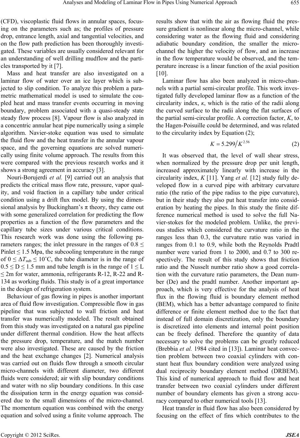 Analyses and Modeling of Laminar Flow in Pipes Using Numerical Approach 655 (CFD), viscoplastic fluid flows in annular spaces, focus- ing on the parameters such as; the profiles of pressure drop, entrance length, axial and tangential velocities, and on the flow path prediction has been thoroughly investi- gated. These variables are usually considered relevant for an understanding of well drilling mudflow and the parti- cles transported by it [7]. Mass and heat transfer are also investigated on a laminar flow of water over an ice layer which is sub- jected to slip condition. To analyze this problem a para- metric mathematical model is used to simulate the cou- pled heat and mass transfer events occurring in moving boundary, problem associated with a quasi-steady state steady flow process [8]. Vapour flow is also analyzed in a concentric annular heat pipe numerically using a simple algorithm. Navier-stoke equation was used to simulate the fluid flow and the heat transfer in the annular vapour space, and the governing equations are solved numeri- cally using finite volume approach. The results from this were compared with the previous research works and it shows a strong agreement in accuracy [3]. Nouri-Borujerdi et al. [9] carried out an analysis that predicts the critical mass flow rate, pressure, vapor qual- ity, and void fraction in a capillary tube under critical condition using a drift flux model. By using the dimen- sional analysis by Buckingham’s π theory, they came out with some generalized correlation for predicting the flow properties as a function of the flow parameters and the capillary tube sizes under various critical conditions. This research work was done using the following pa- rameters ranges; the inlet pressure in the ranges of 0.8 ≤ Pinlet ≤ 1.5 Mpa, the subcooling temperature in the range of 0 ≤ ΔTsub ≤ 10˚C, the tube diameter is in the range of 0.5 ≤ D ≤ 1.5 mm and tube length is in the range of 1 ≤ L ≤ 2m for water, ammonia, refrigerants R-12, R-22 and R- 134 as working fluids. This study is of a great importance in the design of refrigeration system. Behaviour of gas flowing in pipes is another important area of fluid flow investigation. Compressible flow in gas pipeline that was subjected to wall friction and heat transfer was numerically modeled. The result obtained from this study was investigated on a natural gas pipeline under different thermal condition. How the heat affects the pressure drop, temperature, and the match number were also investigated. These are caused by the friction and the heat exchange changes [2]. Numerical analysis was carried out on fluids flow through a smooth circular micro-channels with different diameter, two different fluids were considered; air with slip boundary conditions and water with no slip boundary conditions. In this case the dissipation term in the energy equation was consid- ered due to the small dimensions of the micro-channel. The momentum equation was combined with the energy equation and solved using a finite volume approach. The results show that with the air as flowing fluid the pres- sure gradient is nonlinear along the micro-channel, while considering water as the flowing fluid and considering adiabatic boundary condition, the smaller the micro- channel the higher the velocity of flow, and an increase in the flow temperature would be observed, and the tem- perature increase is a linear function of the axial position [10]. Laminar flow has also been analyzed in micro-chan- nels with a partial semi-circular profile. This work inves- tigated fully developed laminar flow as a function of the circularity index, ĸ, which is the ratio of the radii along the curved surface to the radii along the flat surfaces of the partial semi-circular profile. A correction factor, K, to the Hagen-Poisuille could be determined, and was related to the circularity index by Equation (2); 2.56 5.299KK (2) It was observed that, the level of wall shear stress, when normalized by the pressure drop per unit length, increased approximately linearly with increase in the circularity index, K [11]. Yang et al. [12] study fully de- veloped flow in a curved pipe with arbitrary curvature ratio (the ratio of the pipe radius to the pipe curvature), but in their study they also put heat transfer into consid- eration by heating the pipes. In this study the finite dif- ference numerical method is used to solve the full Na- vier-stokes for the modeled problem. Unlike, the previ- ous studies which considered the curvature ratio in the ranges less than 0.3, the curvature ratio was varied in ranges from 0.1 to 0.9, while both the Reynolds Pradtl number were varied from 1 to 2000, and 0.7 to 300 re- spectively. The result of this study shows that friction ratio and the Nusselt number ratio show a good correla- tion with the curvature ratio parameters, the Dean num- ber (De) and the pradtl number. Another important ap- proach, which is very effective for the analysis of heat flux in the flowing fluid is boundary element method (BEM), which has a better advantage compared to finite difference or finite element method due to the fact that instead of full domain discretization, only the boundary is discretized into elements and internal point position can be freely defined. Therefore the quantity of data necessary to solve the problems can be greatly reduced (Brebbia et al. 1984 cited in [13]). Laminar heat convec- tion problem between two coaxial cylinders with con- stant heat flux boundary condition were analyzed using dual reciprocity boundary element method (DRBEM). This kind of numerical approach to fluid flow and heat transfer between two coaxial cylinders under different number of boundary elements has given a strong accu- racy compared to other numerical tools [13]. Heat transfer in fluid flow has also been considered by focusing on the effect of fins which contributes to the Copyright © 2012 SciRes. JSEA 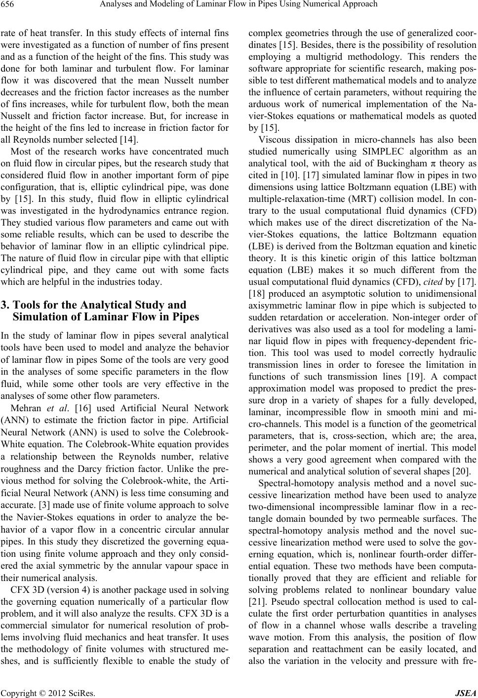 Analyses and Modeling of Laminar Flow in Pipes Using Numerical Approach 656 rate of heat transfer. In this study effects of internal fins were investigated as a function of number of fins present and as a function of the height of the fins. This study was done for both laminar and turbulent flow. For laminar flow it was discovered that the mean Nusselt number decreases and the friction factor increases as the number of fins increases, while for turbulent flow, both the mean Nusselt and friction factor increase. But, for increase in the height of the fins led to increase in friction factor for all Reynolds number selected [14]. Most of the research works have concentrated much on fluid flow in circular pipes, but the research study that considered fluid flow in another important form of pipe configuration, that is, elliptic cylindrical pipe, was done by [15]. In this study, fluid flow in elliptic cylindrical was investigated in the hydrodynamics entrance region. They studied various flow parameters and came out with some reliable results, which can be used to describe the behavior of laminar flow in an elliptic cylindrical pipe. The nature of fluid flow in circular pipe with that elliptic cylindrical pipe, and they came out with some facts which are helpful in the industries today. 3. Tools for the Analytical Study and Simulation of Laminar Flow in Pipes In the study of laminar flow in pipes several analytical tools have been used to model and analyze the behavior of laminar flow in pipes Some of the tools are very good in the analyses of some specific parameters in the flow fluid, while some other tools are very effective in the analyses of some other flow parameters. Mehran et al. [16] used Artificial Neural Network (ANN) to estimate the friction factor in pipe. Artificial Neural Network (ANN) is used to solve the Colebrook- White equation. The Colebrook-White equation provides a relationship between the Reynolds number, relative roughness and the Darcy friction factor. Unlike the pre- vious method for solving the Colebrook-white, the Arti- ficial Neural Network (ANN) is less time consuming and accurate. [3] made use of finite volume approach to solve the Navier-Stokes equations in order to analyze the be- havior of a vapor flow in a concentric circular annular pipes. In this study they discretized the governing equa- tion using finite volume approach and they only consid- ered the axial symmetric by the annular vapour space in their numerical analysis. CFX 3D (version 4) is another package used in solving the governing equation numerically of a particular flow problem, and it will also analyze the results. CFX 3D is a commercial simulator for numerical resolution of prob- lems involving fluid mechanics and heat transfer. It uses the methodology of finite volumes with structured me- shes, and is sufficiently flexible to enable the study of complex geometries through the use of generalized coor- dinates [15]. Besides, there is the possibility of resolution employing a multigrid methodology. This renders the software appropriate for scientific research, making pos- sible to test different mathematical models and to analyze the influence of certain parameters, without requiring the arduous work of numerical implementation of the Na- vier-Stokes equations or mathematical models as quoted by [15]. Viscous dissipation in micro-channels has also been studied numerically using SIMPLEC algorithm as an analytical tool, with the aid of Buckingham π theory as cited in [10]. [17] simulated laminar flow in pipes in two dimensions using lattice Boltzmann equation (LBE) with multiple-relaxation-time (MRT) collision model. In con- trary to the usual computational fluid dynamics (CFD) which makes use of the direct discretization of the Na- vier-Stokes equations, the lattice Boltzmann equation (LBE) is derived from the Boltzman equation and kinetic theory. It is this kinetic origin of this lattice boltzman equation (LBE) makes it so much different from the usual computational fluid dynamics (CFD), cited by [17]. [18] produced an asymptotic solution to unidimensional axisymmetric laminar flow in pipe which is subjected to sudden retardation or acceleration. Non-integer order of derivatives was also used as a tool for modeling a lami- nar liquid flow in pipes with frequency-dependent fric- tion. This tool was used to model correctly hydraulic transmission lines in order to foresee the limitation in functions of such transmission lines [19]. A compact approximation model was proposed to predict the pres- sure drop in a variety of shapes for a fully developed, laminar, incompressible flow in smooth mini and mi- cro-channels. This model is a function of the geometrical parameters, that is, cross-section, which are; the area, perimeter, and the polar moment of inertial. This model shows a very good agreement when compared with the numerical and analytical solution of several shapes [20]. Spectral-homotopy analysis method and a novel suc- cessive linearization method have been used to analyze two-dimensional incompressible laminar flow in a rec- tangle domain bounded by two permeable surfaces. The spectral-homotopy analysis method and the novel suc- cessive linearization method were used to solve the gov- erning equation, which is, nonlinear fourth-order differ- ential equation. These two methods have been computa- tionally proved that they are efficient and reliable for solving problems related to nonlinear boundary value [21]. Pseudo spectral collocation method is used to cal- culate the first order perturbation quantities in analyses of flow in a channel whose walls describe a traveling wave motion. From this analysis, the position of flow separation and reattachment can be easily located, and also the variation in the velocity and pressure with fre- Copyright © 2012 SciRes. JSEA  Analyses and Modeling of Laminar Flow in Pipes Using Numerical Approach 657 quency of excitation can be determined [22]. 4. Application of Laminar Flow Laminar flow has been of a very good important form of flow, this has made its application in most of the science and engineering field to be very useful. Laminar air-flow systems have been used by the aero- space industry to control particulate contamination such as dust or lint which could affect the reliability of preci- sion parts [23]. Laminar flow cabinets were also used to control the level of micro-organisms in a given environ- ment that is to achieve an environment that is free of mi- cro-organisms; the air flowing in such environment must be laminar in nature [23]. In the field of Microbiology laminar flow is applied generally in three major areas, which are: Product protection: In this case laminar flow is ap- plied in the environment such that the product protec- tion is the main goal, that is, where critical sterility and assays are needed, whereby the personnel in such environment is less considered in the design of the laminar air-flow in such environment, that is, the personnel protection is not a problem, Standard hori- zontal laminar flow clean benches can be used for the procedures. Personnel protection: This is an environment where some infectious materials are been processed, in this case for the safety of the technical personnel a verti- cal laminar flow cabinet can be used. Personnel and Product protection: When the mi- crobial contaminants have to be hindered and the per- sonnel have to be protected also, a vertical laminar flow cabinet has to be used [23]. It was also discovered that laminar airflow used in an operating room can yield mean levels of viable airborne contamination at critical sites as low as 0.05 organisms per cubic foot of air [24]. Chen Hua-de et al. found that laminar air flow can be useful in the treatment of burns, by sampling the air in the laminar flow chamber and the wound tissues of the patients for bacteria detection. From their results they concluded that the application of lami- nar air flow to a serious burn can assist in the treatment of the burn, even within a shorter treatment time [25]. 5. Circular Pipe and Elliptical Pipe; Laminar Flow Behaviour Most of the research works focused their attention on the behavior of laminar flow on circular pipes, as less con- sideration has been given elliptical pipes, which is also very important. Circular pipes may deform to an ellipti- cal shape after a series of usage due to temperature and pressure of fluid it conveys over a given period of time, the behavior of flow in the pipe at this time should be clearly known to the engineers. That is how elliptic cy- lindrical pipe contributed to more loss in industries unlike the circular pipes, and the effect of this should be stated so that, time value of a given pipe can be techni- cally determined, and this will help us to understand when a given pipe is due for replacement. However, as some of the important properties of lami- nar flow were not considered in comparison of laminar flow behavior in circular pipe and elliptic cylindrical pipe, [15] still illustrated some comparison between cir- cular and elliptical cylindrical pipes in their research work, these comparisons were enumerated below: To achieve the same mass flow rate in both the circu- lar and elliptic cylindrical pipe, of the same cross- section area, the value of the pressure in the circular pipe has to be increased by almost 50% in the elliptic cylindrical pipe so as to achieve the same mass flow rate as in the circular pipe. In circular pipe the effective wall to wall distance is the same as the hydraulic diameter, Dh. While in el- liptic cylindrical pipe the effective wall to wall dis- tance is over estimated by the hydraulic diameter, Dh. Therefore, this fact of mismatch between the hydrau- lic diameter, Dh, and the effective wall-to-wall dis- tance, explains the reason why the circular pipe as an higher aspect ratio compared to elliptic cylindrical pipe. 6. Conclusion This work has revealed some important applications of laminar flow in pipes, and has also shown that most analyses carried out on laminar flow in pipes were ma- jorly on circular pipe, while less consideration has been given to elliptic cylindrical pipe, which is another im- portant pipe configuration in industries. More so, it has clearly shown how fluid flow is adversely affected by a deformed circular pipe into an elliptic cylindrical shape, by considering the behavior of some of the important flow parameters in these two different pipe configura- tions. This work also shows that some more important flow parameters such as heat transfer etc. are to be con- sidered when analyzing the flow in these two different pipes configuration. This will help the transportation of fluid through circular pipes in industries, by understand- ing the enormous loss that results, when circular pipes are deformed due to usage over time and not been re- placed on time. REFERENCES [1] M. Z. Rad, A. Nouri-Broujerdi and J. Seume, “Numerical Computation of Compressible Laminar Flow with Heat Transfer in the Entrance Region of a Pipe,” Proceeding of 2008 ASME Summer Heat Transfer Conference HT, Jack- Copyright © 2012 SciRes. JSEA  Analyses and Modeling of Laminar Flow in Pipes Using Numerical Approach Copyright © 2012 SciRes. JSEA 658 sonville, 10-14 August 2008. [2] A. Nouri-Broujerdi and M. Ziaei-Rad, “Simulation of Compressible Pipe Flow under Different Thermal Condi- tions,” 2007 ASME-JSME Thermal Engineering Summer Heat Transfer Conference, Vancouver, 8-12 July 2007. [3] A. Nouri-Borujerdi and M. Layeghi, “A Numerical Analysis of Vapor Flow in Concentric Annular Heat Pipes,” Transactions of the ASME, Journal of Fluids En- gineering, Vol. 126, 2004, pp. 442-448. doi:10.1115/1.1760549 [4] V. M. Soundalgekar and V. G. Divekar, “Laminar Slip- Flow through a Uniform Circular Pipe with Small Suc- tion,” Publication de l’Institut Mathematique, Nouvelle Serie, Vol. 16, No. 30, 1993, pp. 147-157. [5] T. Zhao and P. Cheng, “A Numerical Solution of Laminar Forced Convection in a Heated Pipe Subjected to a Re- ciprocating Flow,” International Journal Heat Mass Trans- fer, Vol. 38, No. 16, 1995, pp. 3011-3022. doi:10.1016/0017-9310(95)00017-4 [6] S. K. Karode, “Laminar Flow in Channels with Porous Walls, Revisited,” Journal of Membrane Science, Vol. 191, No. 1, 2001, pp. 237-241. doi:10.1016/S0376-7388(01)00546-4 [7] F. A. R. Pereira1, C. H. Ataíde and M. A. S. Barrozo, “CFD Approach Using a Discrete Phase Model for An- nular Flow Analysis,” Latin American Applied Research, Vol. 40, No. 1, 2010. [8] A. Raoufpanah, “Effect of Slip Condition on the Charac- teristic of Flow in Ice Melting Process,” International Journal of Engineering, Vol. 18, No. 3, 2005, pp. 1-9. [9] A. Nouri-Borujerdi and P. Javidmand, “Critical Mass Flow Rate through Capillary Tubes,” Proceedings of the ASME 2010 3rd Joint US-European Fluids Engineering Summer Meeting and 8th International Conference on Nanochannels, Microchannels, and Minichannels, Mont- real, 1-5 August 2010. [10] A. Nouri and A. Nabovati, “Numerical Study of Viscous Dissipation in Circular Microchannels,” 8th International and 12th Annual Mechanical Engineering Conference, Tarbiat Modarres University, Tehran, 2008. [11] W, J. Federspie and I. Valenti, “Laminar Flow in Micro- Fabricated Channels with Partial Semi-Circular Profiles,” Open Journal of Applied Sciences, Vol. 2, No. 1, 2012, pp. 28-34. doi:10.4236/ojapps.2012.21003 [12] R. Yang and S. F. Chang, “A Numerical Study of Fully Developed Laminar Flow and Heat Transfer in a Curved Pipe with Arbitrary Curvature Ratio,” International Jour- nal of Heat and Fluid Flow, Vol. 14, No. 2, 1993, pp. 138-145. doi:10.1016/0142-727X(93)90021-E [13] I. Sarbu and A. Iosif, “Numerical Analysis of the Laminar Forced Heat Convection between Two Coaxial Cylin- ders,” International Journal of Energy, Vol. 3, No. 4, 2009. [14] N. Yucel and N. Dinler, “Numerical Study on Laminar and Turbulent Flow through a Pipe with Fins Attached,” An International Journal of Computation and Methodol- ogy, Vol. 49, No. 2, 2006, pp. 195-214. [15] M. A. Cade, W. C. P. B. Lima, S. R. Farias Neto and A. G. B. Lima, “Natural Gas Laminar Flow in Elliptic Cy- lindrical Pipes: A Numerical Study,” Brazilian Journal of Petroleum and Gas, Vol. 4, No. 1, 2010, pp. 19-33. [16] M. Yazdi and A. Bardi, “Estimation of Friction Factor in Pipe Flow Using Artificial Neural Networks,” Canadian Journal on Automation, Control & Intelligent Systems, Vol. 2, No. 4, 2011, pp. 52-56. [17] A. Mussa, P. Asinari and L.-S. Luo, “Lattice Boltzmann Simulations of 2D Laminar Flows past Two Tandem Cylinders,” Elsevier Science, New York, 2008. [18] M. S. Ghidaoui and A. A. Kolyshkin, “A Quasi-Steady Approach to the Instability of Time-Dependent Flows in Pipes,” Journal of Fluid Mechanics, Vol. 465, 2002, pp. 301-330. doi:10.1017/S0022112002001076 [19] G. Catania and S. Sorrentino, “Analysis of Frequency- Dependent Friction in Transient Pipe Flow Using Non- Integer Order Derivative Models,” Laboratory of Re- search and Technology Transfer LAV (Laboratory of Acoustics and Vibration), University of Bologna, Bolo- gna, 2007, pp. 1-8. [20] M. Bahrami, M. M. Yovanovich and J. R. Culham, “Pressure Drop of Fully-Developed, Laminar Flow in Micro-Channels of Arbitrary Cross-Section,” Proceed- ings of ICMM 2005 3rd International Conference on Mi- crochannels and Minichannels, Toronto, 13-15 June 2005. [21] Z. G. Makukula, P. Sibanda and S. S. Motsa, “A Novel Numerical Technique for Two-Dimensional Laminar Flow between Two Moving Porous Walls,” Hindawi Publish- ing Corporation Mathematical Problems in Engineering, Vol. 2010, 2010, Article ID: 528956. [22] S. Selvarajan, E .G. Tulapurkara and V. V. Ram, “A Nu- merical Study of Flow through Wavy-Walled Channels,” International Journal for Numerical Methods in Fluids, Vol. 26, 1998, pp. 519-531. doi:10.1002/(SICI)1097-0363(19980315)26:5<519::AID- FLD630>3.0.CO;2-C [23] M. S. Favero and K. R. Berquist, “Use of Laminar Air-Flow Equipment in Microbiology,” Applied Microbi- ology Copyright @ 1968 American Society for Microbi- ology, Vol. 16, No. 1, 1968, pp. 182-183. [24] D. G. Fox, “A Study of the Application of Laminar Flow. Ventilation to Operating Rooms,” Public Health Mono- graph No. 78, US Government Printing Office, Washing- ton, 1969, 58 p. [25] H.-D. Chen, L. Wen, S.-Y. Zheng, H. Gao, B. Xiong, H.-N. Bian, Z.-A. Liu and L.-J. Wel, “Application of Laminar Air Flow Techniques in Burn Treatment,” De- partment of Burn Surgery, People’s Hospital of Guang- dong Province, Guangzhou, 2005. |