

Paper Menu >>
Journal Menu >>
 J. Software Engineering & Applications, 2010, 3, 723-727 doi:10.4236/jsea.2010.37083 Published Online July 2010 (http://www.SciRP.org/journal/jsea) Copyright © 2010 SciRes. JSEA 723 Modeling and Analysis of Submerged Arc Weld Power Supply Based on Double Closed-Loop Control Baoshan Shi1, Kuanfang He2, Xuejun Li2, Dongmin Xiao3 1School of Mechanical and Vehicle Engineering, Beijing Institute of Technology, Zhuhai, China; 2Hunan Provincial Key Laboratory of Health Maintenance for Mechanical Equipment, Xiantan, China; 3College of Electromechanical Engineering, Xiantan, China. Email: [email protected] Received January 6th, 2010; revised May 9th, 2010; accepted May 11th, 2010. ABSTRACT According to the soft-switching pulsed SAW (Submerged arc weld) weld power supply based on the double closed-loop constant current control mode, a small signal mathematic model of main circuit of soft-switching SAW inverter was established by applying the method of three-terminal switching device modeling method, and the mathematic model of double closed-loop phase-shift control system circuit was established by applying the method of state-space averaging method. Dynamic performance of the inverter was analyzed on base of the established mathematic model, and the tested wave of dynamic performance was shown by experimentation. Research and experimentation show that relation be- tween structure of the power source circuit and dynamic performance of the controlling system can be announced by the established mathematic model, which provides development of power supply and optimized design of controlling parameter with theoretical guidance. Keywords: SAW, Double Loop Control, Soft-Switching, Inverter, Mathematic Model 1. Introduction The full-bridge phase-shift zero-voltage soft-switching PWM inverter now is widely used in the weld field for its many excellent performances. Through establishing ma- thematic model and transfer function of soft-switching pulsed metal active gas welding power supply, the rela- tion between structural parameters of circuit and dynamic performance of system is obtained, which is an effective method of designing and development of that power sup- ply [1,2]. In the field of power electronics, problem of linear PWM DC-DC converter modeling was solved, there are many methods of modeling such as three-terminal switching device modeling method, data-sampling, symbol analysis and so on [3-6], and method of space state aver- age applied to inverter modeling [7-10], which provide mathematic model of soft-switching pulsed metal active gas welding power supply with theoretical guidance. This paper proposes a soft-switching SAW weld pow- er supply based on the double closed-loop constant cur- rent control mode, which adopts structure of soft- switching full-bridge circuit and combines the conven- tional negative feedback of current or voltage and the peak current control mode. A small signal mathematic model of main circuit of soft-switching SAW inverter and the mathematic model of double loop control circuit are established by applying the method of three-terminal switching device modeling method and the method of space state average. According to mathematic model, dynamic performance of the inverter is analyzed, and tested wave of dynamic performance is shown to prove the rationality of the inverter by experimentation. 2. Principles The sketch map of the double closed-loop feedback con- trol system is shown in figure1. It uses hall sensor to sample current signal from primary transformer, and pouring into control loop after sophisticated high-speed rectifying. The control loop needs a reasonable slope compensation circuit to ensure the system to be stable and get appropriate open-loop frequency. In the course of operation, the peak current signal )(tis is sampled from the peak current of the VT, then plus a peak current slope compensation signal1 )( fa Rti , which is a signal substituted traditional triangular wave signal in voltage mode control. The saw tooth sig- nal 1 )( fa Rti is synchronized with the signal of inverter cycle, which is mainly used to improve waveform of the  Modeling and Analysis of Submerged Arc Weld Power Supply Based on Double Closed-Loop Control Copyright © 2010 SciRes. JSEA 724 peak current signal, reduce the noises from the power circuit, and advance system stability. Meanwhile, aver- age output current of inductance 2 () L f itR is detected, which is compared to the given signal to get error signal. The error signal is replaced by the given signal of voltage mode control after correcting or compensating, and in- cises the peak current )(tisthat adds saw tooth signal 1 )( fa Rti to adjust duty cycle of VT, which realizes effec- tive control of the output current. The main advantages of inner loop control is to im- prove the overall dynamic response speed of system, protect power tube and realize correction of each current pulse, solve problem of magnetic bias of power trans- former; the purpose of outer loop control is to improve control accuracy and technology of power. 3. Modeling and Analysis 3.1 Mathematical Model of Main Circuit In this paper, mathematical model of main circuit of SAW soft switch inverter is established by the way of three-terminal switching device modeling method. The soft-switching circuit is full-bridge circuit in Figure 1; it is still a typical Buck Converter in essence [11,12]. The main circuit of soft-switching inverter equals to circuit According to three-terminal switching device modeling method in Figure 2(a), dynamic low-frequency small signal circuit model in the pluralism domain is shown in Figure 2(b). According to Figure 2(b), dynamic equations of AC small signal )( ˆsiL of inductance current in pluralism domain are expressed as Equations (1) and (2): ˆ ˆ() () ˆ ˆˆ ()() () () () i i i Li iii U usds DUD D isus ds ZsZs U (1) )(tis 2f R 1f R 1 )( fs Rti 1 )( faRti )(tiL )(tis )(tiL Figure 1. Block diagram of the control system (a) )( 0 Su (b) Figure 2. The AC signal model of main circuit () i Z ssLR (2) Equations (3) and (4) are dynamic equations of small signal of output voltage in pluralism domain. ˆ ˆ()() () oLo us isZs (3) () o Z sR (4) From above equations, the transfer function for rela- tion between output current of load and duty cycle can be denoted as Equation (5): 1 1 )( ˆ )( ˆ )( 0)( ˆ s R L R U RsL U sd si sG ii su L id i (5) The transfer function for relation between output cur- rent of load and duty cycle can be denoted as Equation (6): ˆ() 0 ˆ() () () ˆ() 1 i oi udu sid us U Gs GsRL ds s R (6) In Equations (5) and (6), Ui is the equivalent DC input voltage; L is the output filter inductance; R is load resis- tance. Main circuits of inverter are composed of propor- tional part and inertia part in view of control structure. 3.2 Mathematical Modeling of Inner Loop Control System The structure of control circuit of inner loop current is shown in Figure 3. The inductance current iL(t) is gained by input voltage ui(t) and output voltage uo(t), iL(t)plus resistor Rf and then change into voltage signals iL(t)Rf. iL(t)Rf plus the slope compensated voltage ua(t),which import to the negative terminal of PWM comparator. uc(t) is reference voltage of positive terminal of PWM com- parator. Relations expression of duty cycle d and input  Modeling and Analysis of Submerged Arc Weld Power Supply Based on Double Closed-Loop Control Copyright © 2010 SciRes. JSEA 725 u o (t) u i (t) i L (t)R f R f u c (t) i L (t) PWM comparator Ratio of switch d u a (t) (a) H 0 A C E T s v c B F D i L (t)R f u -m 2 m 1 -m a u c t dT s (b) Figure 3. Model of current-injection controller voltage ui(t), output voltage uo(t), slope compensation voltage ua(t), reference voltage uc(t) and inductance cur- rent iL(t) are derivatived by application of Space State Average method. From Figure 3(b), we can indicates expression of av- erage voltage of inductance sampling current in the opening of each cycle as Equation (7). 0 () 11 fLavg Ts f LABEF ACHBDH ss Ri t Ridt SSS TT (7) In the Equation (7), SABEF、S ACH and S BDH are the area of rectangular ABEF, triangle ACH and the tri- angle BDH in Figure 3(b), according to Equation (7), we have Equation (8): 2 2 12 () 11 () 1 22 fLavg cas ss Ri t utmdTmdTmd T (8) In Equation (8), we can obtain Equation (10) after adding disturbing variable and taking into account that the system state has no relation to the slope compensa- tion voltage shown in Equation (9). aa Mtm)( (9) 2 11 ˆ() 1 ˆˆ ˆˆ ()()() () 2 fL L cc ass RI it Uut MDdtTMmtDdtT 2 22 1ˆ ˆ() 1() 2 s M mtDdt T (10) In Equation (10), )( ˆtiL、)( ˆtuc、)( ˆtd 、)( ˆ1tm 、and )( ˆ2tm are corresponding disturbing variable .We can ob- tain Equation (11) after linear treatment of Equation (10) 2 212 ˆ() 11 ˆ ˆˆˆ ()()() 1() 22 fL casss Ri t utMTdtDTmtD Tmt (11) In view of equation of L uu Rm oi f ˆˆ ˆ1 and equation of L u Rm o f ˆ ˆ2 in Buck Converter, the transfer function of inner peak current control circuit shown in Equation (12) can be obtained from Equation (11). 2 ˆ() (1 2 ) 1ˆ ˆˆˆ () ()()() 22 fsf s cfL io as ds RDTR DT us Risusus MTL L (12) 3.3 Mathematical Model of Double Closed-Loop Control System In order to improve accuracy of control system, reduce steady error, the average output current or voltage are sampled in this control system, and compared to the in- ner given compensation signal uc(s). Primarily role of outer loop regulator is to improve and optimize system performance; PI regulator is used in this paper. Accord- ing to Subsection 3.1 and Subsection 3.2, overall control system diagram based on model of double closed-loop current is shown in Figure 4, the DC signal ui(s) can be treated as system disturbance. According to Figure 4, open-loop transfer function of the inner loop current is expressed as Equation (13). )( ˆsu i L TDR TM U D f sa i 2 2 a if sa i LM DUR RLs TM U 2 )21( 1 1 )(siL S TSK)1( 2 f R 1 K )(si L )(su e )( ˆsu c Figure 4. Block diagram of the double loop system  Modeling and Analysis of Submerged Arc Weld Power Supply Based on Double Closed-Loop Control Copyright © 2010 SciRes. JSEA 726 1 1 (1 2 ) [1 ] 2 fi fi aS a RU GS RU D MT LS RLM (13) Equation (14) is inner closed-loop transfer function. 1 () () () (1 2 ) 2 L c i fi S asasf i is Ws us U RRUDT M TLsM RTRU L (14) Equation (15) is transfer functions of entire open dou- ble closed-loop system. 211 12 (1) ()( ) 11 (1 2 ) 2 ifi s asasf i KTS GsW SK S TS KKU RRUD T S M TLSMRTRU L (15) Equation (16) is transfer functions of closed-loop transfer function for the entire system. 2 12 () (1) (1 2 ) ()(1) 2 i fi s aSasf ii WS KU TS RRUD T SMTLSM RTRUKKUTS L (16) In Equation (16), D is duty cycle; Ui is inputting DC voltage; TS is the inverting cycle; Rf is sampling resistor of the inner current; Ma is the rising slope of compensa- tion voltage; L is Output filter inductance; R is pulsed arc load; K1 is feedback coefficient of outer loop current; K2 is adjusting gain; T is time constants of regulator. 3.4 Analysis of Dynamic Characteristic The cutoff frequency of open-loop that is an important characteristic index that is the embodiment of dynamic response of control system [13]. Dynamic characteristic of welding power are analyzed as mathematical model established in Subsection 3.3. Provided outer loop is a simple proportional control mode, and the open-loop system fc is frequency when open loop gain equals to1, according to Equation (15), and set1)2( c fjG , we have: 12 (2 ) 11 (1 2 ) 21 2 c i fifi as c a Gj f KKU RVD RU MT Lj f RLM R (17) In this paper (1 2 ) 21 2 f ifi c a RVD RU Lj fRLM R , Equation (17) can be taken form as following: LTM UKK f sa i c 2 21 (18) In Equation (18), open-loop traversing frequencyc fis proportional of outer loop resistor, DC input voltage and gain of outer loop adjuster. But the traversing open-loop frequency is inversely proportional to the rising rate of compensation voltage, switching cycle and output induc- tance. Since outer loop resistor is limited by linear ad- justment range of voltage of control circuit, opening tra- versing frequency of control system can be increased by the way of reducing rising ratio of compensation voltage and output inductance, and increasing frequency of in- verter. From above analysis, dynamic response of double closed loop control system is improved greatly by inner loop current control. 4. Experimentation Dynamic characteristics of arc welding inverter are al- ways defined as the relationship between output current or output voltage and time when load instantaneous change, which is a major performance index of arc weld power source. Two sets of experiments of constant cur- rent outer characteristic of arc weld power source are done to prove the effect of theatrical analysis based on the double closed-loop constant current control mode. The experiments of arc welding are current response un- der condition of the instantaneous change of the given signal and current response under condition of instanta- neous change of the given load. The curve of Figure 5 is current response when cur- rent instantaneous change from 0 A to 430 A under the simulated load of 0.1 . In figure5, the current instanta- neous change from 50 A to 320 A just needs time of 2 ms, which conclude that system has better dynamic perform- ance through this experimentation. The curve of Figure 6 is current response curve meas- ured by given current value of 100A and simulated load changing from 0.09 to 0.03 . In Figure 6, the given current instantaneous change from 130 A to 100 A just needs time of 4 ms, which conclude that system has bet- ter dynamic performance and a constant current outer characteristic. 5. Conclusions Mathematical model of SAW weld soft-switching in- verter based on a double closed-loop constant voltage and current control is established. Based on mathematical model, dynamic performance is analyzed, and dynamic characteristic curve of arc weld power source is tested in 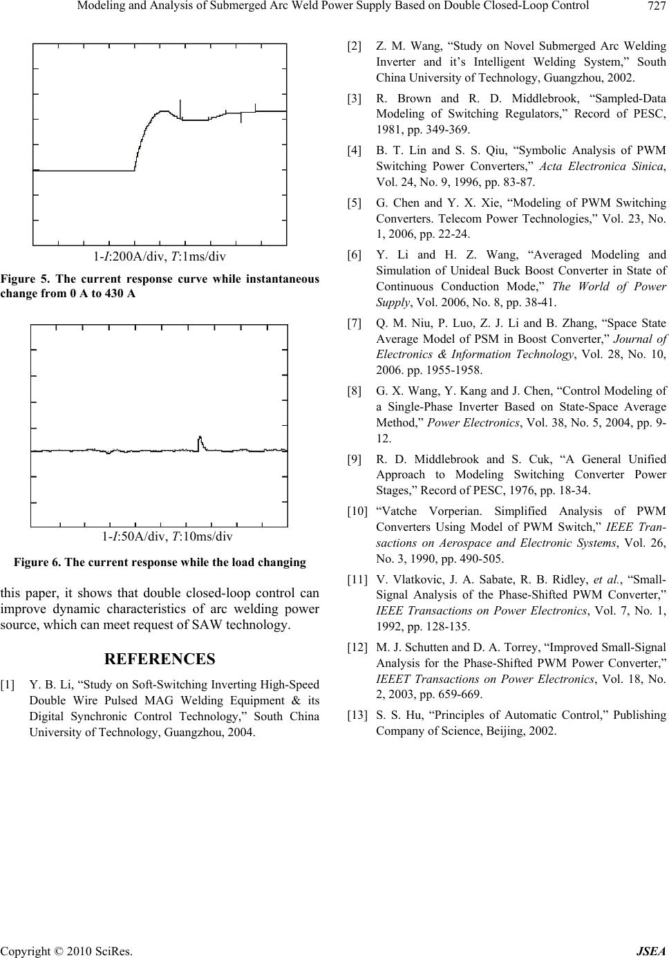 Modeling and Analysis of Submerged Arc Weld Power Supply Based on Double Closed-Loop Control Copyright © 2010 SciRes. JSEA 727 1 - I :20 0 A/div, T : 1 ms/div Figure 5. The current response curve while instantaneous change from 0 A to 430 A 1-I:50A/div, T:10ms/div Figure 6. The current response while the load changing this paper, it shows that double closed-loop control can improve dynamic characteristics of arc welding power source, which can meet request of SAW technology. REFERENCES [1] Y. B. Li, “Study on Soft-Switching Inverting High-Speed Double Wire Pulsed MAG Welding Equipment & its Digital Synchronic Control Technology,” South China University of Technology, Guangzhou, 2004. [2] Z. M. Wang, “Study on Novel Submerged Arc Welding Inverter and it’s Intelligent Welding System,” South China University of Technology, Guangzhou, 2002. [3] R. Brown and R. D. Middlebrook, “Sampled-Data Modeling of Switching Regulators,” Record of PESC, 1981, pp. 349-369. [4] B. T. Lin and S. S. Qiu, “Symbolic Analysis of PWM Switching Power Converters,” Acta Electronica Sinica, Vol. 24, No. 9, 1996, pp. 83-87. [5] G. Chen and Y. X. Xie, “Modeling of PWM Switching Converters. Telecom Power Technologies,” Vol. 23, No. 1, 2006, pp. 22-24. [6] Y. Li and H. Z. Wang, “Averaged Modeling and Simulation of Unideal Buck Boost Converter in State of Continuous Conduction Mode,” The World of Power Supply, Vol. 2006, No. 8, pp. 38-41. [7] Q. M. Niu, P. Luo, Z. J. Li and B. Zhang, “Space State Average Model of PSM in Boost Converter,” Journal of Electronics & Information Technology, Vol. 28, No. 10, 2006. pp. 1955-1958. [8] G. X. Wang, Y. Kang and J. Chen, “Control Modeling of a Single-Phase Inverter Based on State-Space Average Method,” Power Electronics, Vol. 38, No. 5, 2004, pp. 9- 12. [9] R. D. Middlebrook and S. Cuk, “A General Unified Approach to Modeling Switching Converter Power Stages,” Record of PESC, 1976, pp. 18-34. [10] “Vatche Vorperian. Simplified Analysis of PWM Converters Using Model of PWM Switch,” IEEE Tran- sactions on Aerospace and Electronic Systems, Vol. 26, No. 3, 1990, pp. 490-505. [11] V. Vlatkovic, J. A. Sabate, R. B. Ridley, et al., “Small- Signal Analysis of the Phase-Shifted PWM Converter,” IEEE Transactions on Power Electronics, Vol. 7, No. 1, 1992, pp. 128-135. [12] M. J. Schutten and D. A. Torrey, “Improved Small-Signal Analysis for the Phase-Shifted PWM Power Converter,” IEEET Transactions on Power Electronics, Vol. 18, No. 2, 2003, pp. 659-669. [13] S. S. Hu, “Principles of Automatic Control,” Publishing Company of Science, Beijing, 2002. |