

Paper Menu >>
Journal Menu >>
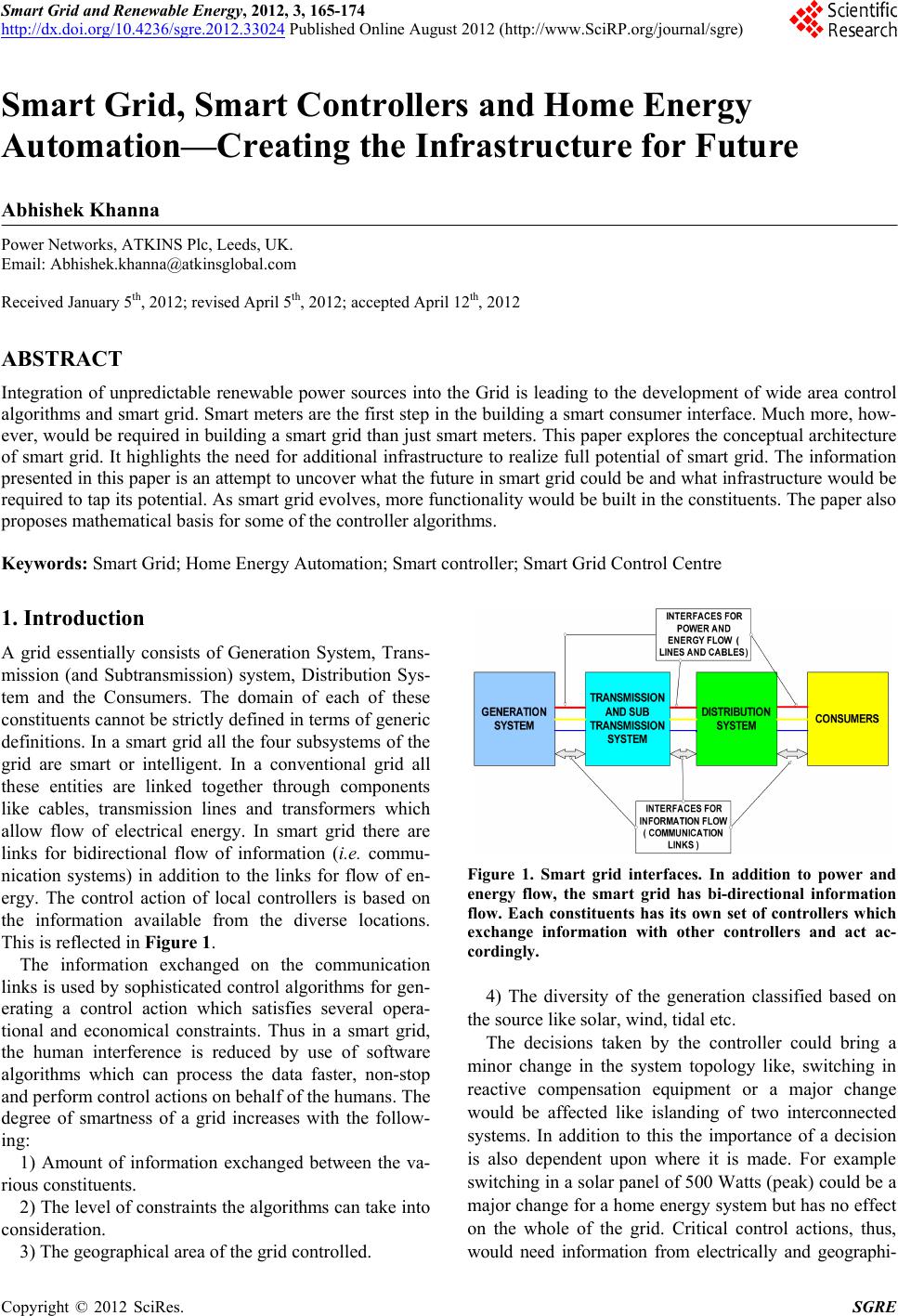 Smart Grid and Renewable Energy, 2012, 3, 165-174 http://dx.doi.org/10.4236/sgre.2012.33024 Published Online August 2012 (http://www.SciRP.org/journal/sgre) 165 Smart Grid, Smart Controllers and Home Energy Automation—Creating the Infrastructure for Future Abhishek Khanna Power Networks, ATKINS Plc, Leeds, UK. Email: [email protected] Received January 5th, 2012; revised April 5th, 2012; accepted April 12th, 2012 ABSTRACT Integration of unpredictable renewable power sources into the Grid is leading to the development of wide area control algorithms and smart grid. Smart meters are the first step in the build ing a smart consumer interface. Much more, how- ever, would be required in building a smart grid than just smart meters. This paper explores the conceptual architecture of smart grid. It highlights the need for additional infrastructure to realize full potential of smart grid. The information presented in this pap er is an attempt to uncover what the futu re in smart grid could be and what infrastructure would be required to tap its potential. As smart g rid evolves, more function ality would be built in the co nstituents. The pape r also proposes mathematical basis for some of the controller algorith ms. Keywords: Smart Grid; Home Energy Automation; Smart controller; Smart Grid Control Centre 1. Introduction A grid essentially consists of Generation System, Trans- mission (and Subtransmission) system, Distribution Sys- tem and the Consumers. The domain of each of these constituents cannot be strictly defined in terms of gen eric definitions. In a smart grid all the four subsystems of the grid are smart or intelligent. In a conventional grid all these entities are linked together through components like cables, transmission lines and transformers which allow flow of electrical energy. In smart grid there are links for bidirectional flow of information (i.e. commu- nication systems) in addition to the links for flow of en- ergy. The control action of local controllers is based on the information available from the diverse locations. This is reflected in Figure 1. The information exchanged on the communication links is used by sophisticated control algorithms for gen- erating a control action which satisfies several opera- tional and economical constraints. Thus in a smart grid, the human interference is reduced by use of software algorithms which can process the data faster, non-stop and perform control actions on behalf of the humans. The degree of smartness of a grid increases with the follow- ing: 1) Amount of information exchanged between the va- rious constituents. 2) The level of constraints the algorithms can take into consideration. 3) The geographical area of the grid controlled. Figure 1. Smart grid interfaces. In addition to power and energy flow, the smart grid has bi-directional information flow. Each constituents has its own set of controllers which exchange information with other controllers and act ac- cordingly. 4) The diversity of the generation classified based on the source like solar, wind, tidal etc. The decisions taken by the controller could bring a minor change in the system topology like, switching in reactive compensation equipment or a major change would be affected like islanding of two interconnected systems. In addition to this the importance of a decision is also dependent upon where it is made. For example switching in a solar panel of 500 Watts (peak) could be a major change for a home energy system but has no effect on the whole of the grid. Critical control actions, thus, would need information from electrically and geographi- Copyright © 2012 SciRes. SGRE 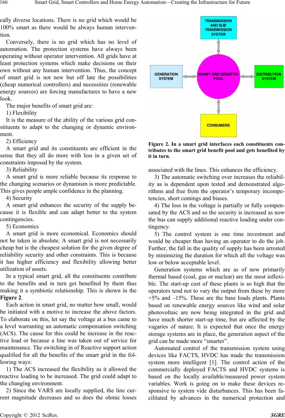 Smart Grid, Smart Controllers and Home Energy Automation—Creating the Infrastructure for Future 166 cally diverse locations. There is no grid which would be 100% smart as there would be always human interven- tion. Conversely, there is no grid which has no level of automation. The protection systems have always been operating without operator intervention. All grids have at least protection systems which make decisions on their own without any human intervention. Thus, the concept of smart grid is not new but off late the possibilities (cheap numerical controllers) and necessities (renewable energy sources) are forcing manufactures to have a new look. The major benefits of smart grid are: 1) Flexibility It is the measure of the ability of the v arious grid con- stituents to adapt to the changing or dynamic environ- ment. 2) Efficiency A smart grid and its constituents are efficient in the sense that they all do more with less in a given set of constraints imposed by the system. 3) Reliability A smart grid is more reliable because its response to the changing scenarios or dynamism is more predictable. This gives people ample confidence in the planning. 4) Security A smart grid enhances the security of the supply be- cause it is flexible and can adapt better to the system contingencies. 5) Economics A smart grid is more economical. Economics should not be taken in absolute. A smart grid is not necessarily cheap but is the cheapest solution for the given degree of reliability security and other constraints. This is because it has higher efficiency and flexibility allowing better utilization of assets. In a typical smart grid, all the constituents contribute to the benefits and in turn get benefited by them thus making it a symbiotic relationship. This is shown in the Figure 2. Each action in smart grid, no matter how small, would be initiated with a motive to increase the above factors. To elaborate on this, let say the voltage at a bus came to a level warranting an automatic compensation switching (ACS). The cause for this could be increase in the reac- tive load or because a line was taken out of service for maintenance. The switching in of Reactive support action qualified for all the benefits of the smart grid in the fol- lowing ways: 1) The ACS increased the flexibility as it allowed the reactive loading to be increased. The grid could adapt to the changing environment. 2) Since the VARS are locally supplied, the line cur- rent magnitude decreases and so does the ohmic losses Figure 2. In a smart grid interfaces each constituents con- tributes to the smart grid benefit pool and gets benefited by it in turn. associated with the lines. This enhances the efficiency. 3) The automatic switching over increases the reliabil- ity as is dependent upon tested and demonstrated algo- rithms and free from the operator’s temporary incompe- tencies, short comings and biases. 4) The loss in the voltage is partially or fully compen- sated by the ACS and so the security is increased as now the bus can supply additional reactive loading under con- tingency. 5) The control system is one time investment and would be cheaper than having an operator to do the job. Further, the fall in the quality of supply has been arrested by minimizing the duration for which all the voltage was low or below acceptable level. Generation systems which are as of now primarily thermal based (coal, gas or nuclear) are the most inflexi- ble. The start-up cost of these plants is so high that the operators tend not to vary the output from these by more +5% and –15%. These are the base loads plants. Plants based on renewable energy sources like wind and solar photovoltaic are now being integrated in the grid and have much shorter start-up time, but are affected by the vagaries of nature. It is expected that once the energy storage systems are in place, the generation aspect of the grid can be made more “smarter”. Automated control of the transmission system using devices like FACTS, HVDC has made the transmission system more intelligent [1]. The control action of the commercially deployed FACTS and HVDC systems is based on the locally available/measured power system variables. Work is going on to make these devices re- sponsive to system vide disturbances. This has been fa- cilitated by advances in the numerical protection and Copyright © 2012 SciRes. SGRE 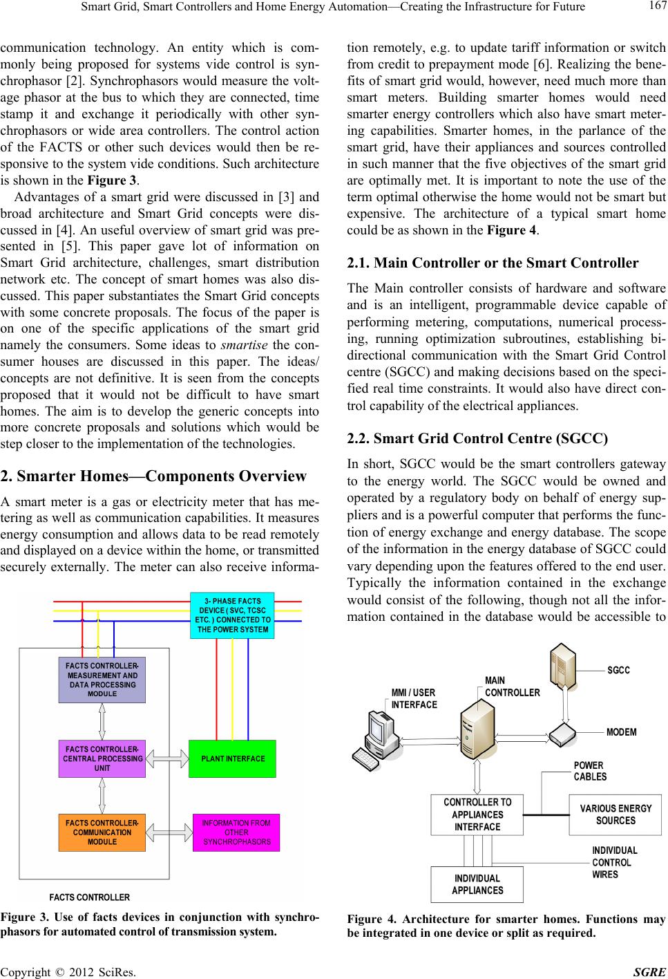 Smart Grid, Smart Controllers and Home Energy Automation—Creating the Infrastructure for Future 167 communication technology. An entity which is com- monly being proposed for systems vide control is syn- chrophasor [2]. Synchrophasors would measure the volt- age phasor at the bus to which they are connected, time stamp it and exchange it periodically with other syn- chrophasors or wide area controllers. The control action of the FACTS or other such devices would then be re- sponsive to the system vid e conditions. Such architecture is shown in the Figure 3. Advantages of a smart grid were discussed in [3] and broad architecture and Smart Grid concepts were dis- cussed in [4]. An useful overview of smart grid was pre- sented in [5]. This paper gave lot of information on Smart Grid architecture, challenges, smart distribution network etc. The concept of smart homes was also dis- cussed. This paper substantiates the Smart Grid concepts with some concrete proposals. The focus of the paper is on one of the specific applications of the smart grid namely the consumers. Some ideas to smartise the con- sumer houses are discussed in this paper. The ideas/ concepts are not definitive. It is seen from the concepts proposed that it would not be difficult to have smart homes. The aim is to develop the generic concepts into more concrete proposals and solutions which would be step closer to the implementation of the technologies. 2. Smarter Homes—Components Overview A smart meter is a gas or electricity meter that has me- tering as well as communication capab ilities. It measures energy consumption and allows data to be read remotely and displayed on a device within the home, or transmitted securely externally. The meter can also receive informa- Figure 3. Use of facts devices in conjunction with synchro- phasors for automated control of transmission system. tion remotely, e.g. to update tariff information or switch from credit to prepayment mode [6]. Realizing the bene- fits of smart grid would, however, need much more than smart meters. Building smarter homes would need smarter energy controllers which also have smart meter- ing capabilities. Smarter homes, in the parlance of the smart grid, have their appliances and sources controlled in such manner that the five objectives of the smart grid are optimally met. It is important to note the use of the term optimal otherwise the home would not be smart but expensive. The architecture of a typical smart home could be as shown in the Figure 4. 2.1. Main Controller or the Smart Controller The Main controller consists of hardware and software and is an intelligent, programmable device capable of performing metering, computations, numerical process- ing, running optimization subroutines, establishing bi- directional communication with the Smart Grid Control centre (SGCC) and making decisions based on the speci- fied real time constraints. It would also have direct con- trol capability of the electrical app liances. 2.2. Smart Grid Control Centre (SGCC) In short, SGCC would be the smart controllers gateway to the energy world. The SGCC would be owned and operated by a regulatory body on behalf of energy sup- pliers and is a powerful computer that performs the func- tion of energy exchange and energy database. The scope of the information in the energy database of SGCC could vary depending upon the features offered to the end user. Typically the information contained in the exchange would consist of the following, though not all the infor- mation contained in the database would be accessible to Figure 4. Architecture for smarter homes. Functions may be integrated in one device or split as required. Copyright © 2012 SciRes. SGRE 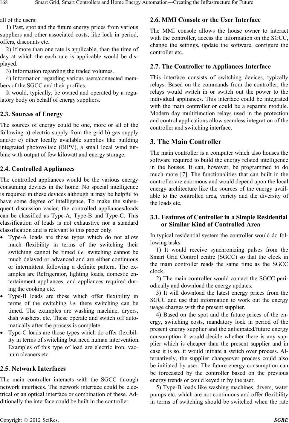 Smart Grid, Smart Controllers and Home Energy Automation—Creating the Infrastructure for Future 168 all of the users: 1) Past, spot and the future energy prices from various suppliers and other associated costs, like lock in period, offers, discounts etc. 2) If more than one rate is applicable, than the ti me of day at which the each rate is applicable would be dis- played. 3) Information regarding the traded volumes. 4) Information regarding various users/connected mem- bers of the SGCC and their profiles. It would, typically, be owned and operated by a regu- latory body on beh a lf of energy suppliers. 2.3. Sources of Energy The sources of energy could be one, more or all of the following a) electric supply from the grid b) gas supply and/or c) other locally available supplies like building integrated photovoltaic (BIPV), a small local wind tur- bine with output of few kilowatt and energy storage. 2.4. Controlled Appliances The controlled appliances would be the various energy consuming devices in the home. No special intelligence is required in these devices although it may be helpful to have some degree of intelligence. To make the subse- quent discussion easier, the controlled appliances/loads can be classified as Type-A, Type-B and Type-C. This classification of loads is not exhaustive nor a standard classification and is relevan t to this paper only. Type-A loads are those types which do not allow much flexibility in terms of the switching their switching cannot be timed i.e. switching cannot be much delayed or advanced and are either continuous or intermittent following a definite pattern. The ex- amples are Refrigerator, lighting loads, domestic en- tertainment appliances, and appliances required dur- ing the cooking etc. Type-B loads are those which offer flexibility in terms of the switching i.e. there switching can be timed. The examples are washing machine, dryers, dish washers, etc. These operate and switch off auto- matically after the process is complete. Type-C loads are those types which do offer flexibil- ity in terms of switching but need human intervention. Examples of this type of load are electric iron, vac- uum cleaners etc. 2.5. Network Interfaces The main controller interacts with the SGCC through network interfaces. The network interface could be elec- trical or an optical interface or combination of these. Ad- ditionally the interface could be built in the controller. 2.6. MMI Console or the User Interface The MMI console allows the house owner to interact with the controller, access the information on the SGCC, change the settings, update the software, configure the controller etc. 2.7. The Controller to Appliances Interface This interface consists of switching devices, typically relays. Based on the commands from the controller, the relays would switch in or switch out the power to the individual appliances. This interface could be integrated with the main controller or could be a separate module. Modern day multifunction relays used in the protection and control application s allow seamless integration of the controller and switc hing interface. 3. The Main Controller The main controller is a computer which also houses the software required to build the energy related intelligence in the houses. It can, however, be programmed to do much more [7]. The functionalities that can built in the controller are enormous and would depend upon the local energy architecture like the sources of the energy avail- able to the controlled area, variety and the diversity of the loads etc. 3.1. Features of Controller in a Simple Residential or Similar Kind of Controlled Area In typical residential system the controller would do fol- lowing tasks: 1) It would receive synchronizing pulses from the Smart Grid Control centre (SGCC) so that the clock in the main controller reads the same time as the SGCC clock. 2) The main controller would contact the SGCC peri- odically and download the energy updates. 3) It will download the latest energy prices from the SGCC and use that information to work out the energy usage charges with the present supplier. 4) Based on the spot and the future prices of the en- ergy, switching costs, mandatory lock in period of the present energy supplier and the anticipated/future energy consumption it would decide whether there is any sup- plier which is cheaper than the present supplier and in case it is so, it would initiate a switch over process. Al- ternatively, the supplier changeover process could also be initiated by user. The future energy consumption can be forecasted by the controller based on the previous energy trends or could keyed in by the user. 5) Type-B loads like washing machines, dryers, water pumps etc. which are not contin uous and offer flexibility in terms of switching should be switched when the rate Copyright © 2012 SciRes. SGRE 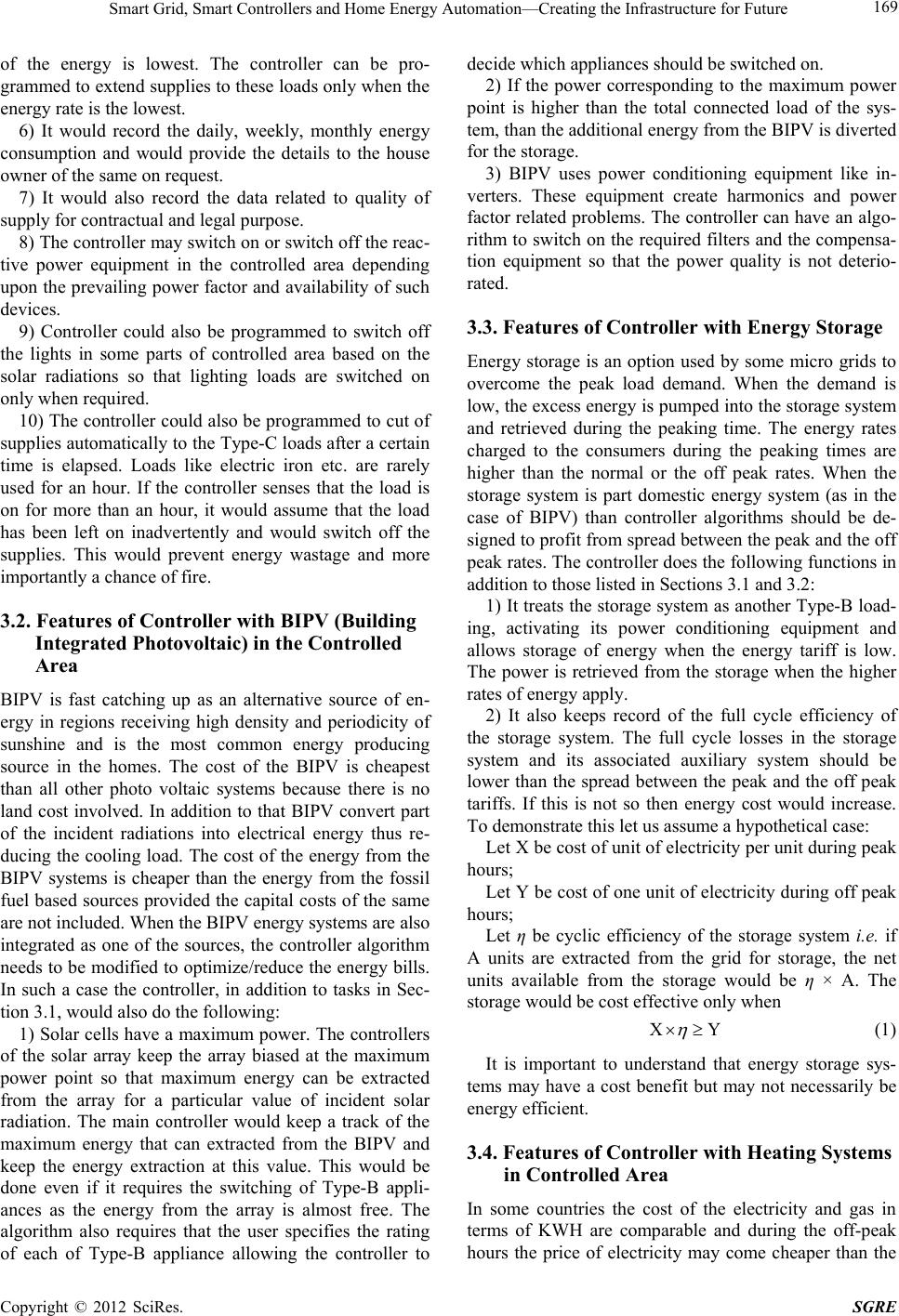 Smart Grid, Smart Controllers and Home Energy Automation—Creating the Infrastructure for Future 169 of the energy is lowest. The controller can be pro- grammed to extend su pplies to these load s only when the energy rate is the lowest. 6) It would record the daily, weekly, monthly energy consumption and would provide the details to the house owner of the same on request. 7) It would also record the data related to quality of supply for contractual and legal purpose. 8) The controller may switch on or switch off the reac- tive power equipment in the controlled area depending upon the prev ailing power factor and availability o f such devices. 9) Controller could also be programmed to switch off the lights in some parts of controlled area based on the solar radiations so that lighting loads are switched on only when required. 10) The controller could also be programmed to cut of supplies automatically to the Typ e-C loads after a certain time is elapsed. Loads like electric iron etc. are rarely used for an hour. If the controller senses that the load is on for more than an hour, it would assume that the load has been left on inadvertently and would switch off the supplies. This would prevent energy wastage and more importantly a chance of fire. 3.2. Features of Controller with BIPV (Building Integrated Photovoltaic) in the Controlled Area BIPV is fast catching up as an alternative source of en- ergy in regions receiving high density and periodicity of sunshine and is the most common energy producing source in the homes. The cost of the BIPV is cheapest than all other photo voltaic systems because there is no land cost involved. In addition to that BIPV convert part of the incident radiations into electrical energy thus re- ducing the cooling load. The cost of the energy from the BIPV systems is cheaper than the energy from the fossil fuel based sources provided the capital costs of the same are not included. When the BIPV energy systems are also integrated as one of the sources, the controller algorithm needs to be modified to optimize/red uce the energy bills. In such a case the controller, in addition to tasks in Sec- tion 3.1, would also do the fol l owi n g: 1) Solar cells have a maximum power. The controllers of the solar array keep the array biased at the maximum power point so that maximum energy can be extracted from the array for a particular value of incident solar radiation. The main controller would keep a track of the maximum energy that can extracted from the BIPV and keep the energy extraction at this value. This would be done even if it requires the switching of Type-B appli- ances as the energy from the array is almost free. The algorithm also requires that the user specifies the rating of each of Type-B appliance allowing the controller to decide which appliances should be switched on. 2) If the power corresponding to the maximum power point is higher than the total connected load of the sys- tem, than the additional en ergy fro m the BIPV is diverted for the storage. 3) BIPV uses power conditioning equipment like in- verters. These equipment create harmonics and power factor related problems. The controller can have an algo- rithm to switch on the required filters and the compensa- tion equipment so that the power quality is not deterio- rated. 3.3. Features of Controller with Energy Storage Energy storage is an option used by some micro grids to overcome the peak load demand. When the demand is low, the excess energy is pumped into the storage system and retrieved during the peaking time. The energy rates charged to the consumers during the peaking times are higher than the normal or the off peak rates. When the storage system is part domestic energy system (as in the case of BIPV) than controller algorithms should be de- signed to pr ofit fro m spre ad between th e peak and the off peak rates. The controller does the fo llowing functions in addition to those listed in Sections 3.1 and 3.2: 1) It trea ts the storage sys tem as another Type-B load- ing, activating its power conditioning equipment and allows storage of energy when the energy tariff is low. The power is retrieved from the storage when the higher rates of energy apply. 2) It also keeps record of the full cycle efficiency of the storage system. The full cycle losses in the storage system and its associated auxiliary system should be lower than the spread between the peak and the off peak tariffs. If this is not so then energy cost would increase. To demonstrate this let us assume a hypothetical case: Let X be cost of unit of electricity per unit during peak hours; Let Y be cost of one unit of electricity during off peak hours; Let η be cyclic efficiency of the storage system i.e. if A units are extracted from the grid for storage, the net units available from the storage would be η × A. The storage would be cost effective only when XY (1) It is important to understand that energy storage sys- tems may have a cost benefit but may not necessarily be energy efficient. 3.4. Features of Controller with Heating Systems in Controlled Area In some countries the cost of the electricity and gas in terms of KWH are comparable and during the off-peak hours the price of electricity may come cheaper than the Copyright © 2012 SciRes. SGRE 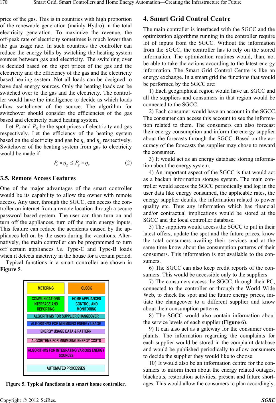 Smart Grid, Smart Controllers and Home Energy Automation—Creating the Infrastructure for Future 170 price of the gas. This is in countries with high proportion of the renewable generation (mainly Hydro) in the total electricity generation. To maximize the revenue, the off-peak rate of electricity sometimes is much lower than the gas usage rate. In such countries the controller can reduce the energy bills by switching the heating system sources between gas and electricity. The switching over is decided based on the spot prices of the gas and the electricity and the efficiency of the gas and the electricity based heating system. Not all loads can be designed to have dual energy sources. Only the heating loads can be switched over to the gas and the electricity. The control- ler would have the intelligence to decide as which loads allow switchover of the source. The algorithm for switchover should consider the efficiencies of the gas based and electricity based heating system. Let Pe and Pg be the spot prices of electricity and gas respectively. Let the efficiency of the heating system based on the electricity and gas be ηe and ηg respectively. Switchover of the heating system from gas to electricity would be made if eg g PP e (2) 3.5. Remote Access Features One of the major advantages of the smart controller would be its capability to allow the owner with remote access. Any user, through the SGCC, can access the con- troller on internet from a remote location through a secure password based system. The user can than turn on and turn off the appliances, turn off the main energy inputs. This feature can reduce the accidents caused by the ap- pliances left on by the users during the vacations. Alter- natively, the main controller can be programmed to turn off certain appliances i.e. Type-C and Type-B loads when it detects inactivity in the house for a certain p eriod. Typical functions in a smart controller are shown in Figure 5. Figure 5. Typical functions in a smart home c ontroller . 4. Smart Grid Control Centre The main controller is interfaced with the SGCC an d the optimization algorithms running in the controller require lot of inputs from the SGCC. Without the information from the SGCC, the controller has to rely on the stored information. The optimization routines would, than, not be able to take the actions according to the latest energy information. The Smart Grid Control Centre is like an energy exchange. In a smart grid the functions that would be performed by the SGCC are: 1) Each geographical region would have an SGCC and all the suppliers and consumers in that region would be connected to the SGCC. 2) Each consumer w ould have an accoun t in the SG CC. The consumer can access this account to see the informa- tion related to them. The consumers can also forecast their energy consumption and inform the energy supplier about the forecasts through the SGCC. Based on the ac- curacy of the forecasts the supplier may chose to reward the consumer. 3) It would act as an energy database storing informa- tion about the energy system. 4) An important aspect of the SGCC is that would act as a backup information storage system. The main con- troller would access the SGCC periodically and log in the user data like energy consumed, the applicable rates, the energy supplier details, the information related to power quality etc. Thus any information which has financial and/or contractual implications would be stored at the SGCC and the local controller da tabase. 5) The suppliers would access the SGCC to put in their latest offers, update the spot and the future prices, know the total consumers availing their services and at the same time know about the consumption patterns of their consumers. This information is not available to the con- sumers. 6) The SGCC can also keep credit reports of the con- sumers. This would be accessible only to the suppliers. 7) The consumers access the SGCC, through their PC, connected to the controller or through the World Wide Web, to check the spot and the future energy prices, ini- tiate the changeover to a different supplier and know about their consumption patterns. 8) The SGCC would also contain information about the service levels of each supplier (Figure 6). 9) It can also act as a gateway for the consumer com- plaints. The information regarding the complaints for each supplier would be stored in the complaint database and would be published periodically to allow consumers to decide the supplier they would like to choose. 10) It would also be an information centre for the con- sumers to inform them about the energy related outages, blackouts, restoration activities, present and future short- ages. This would allow the consumers to plan accordingly. Copyright © 2012 SciRes. SGRE 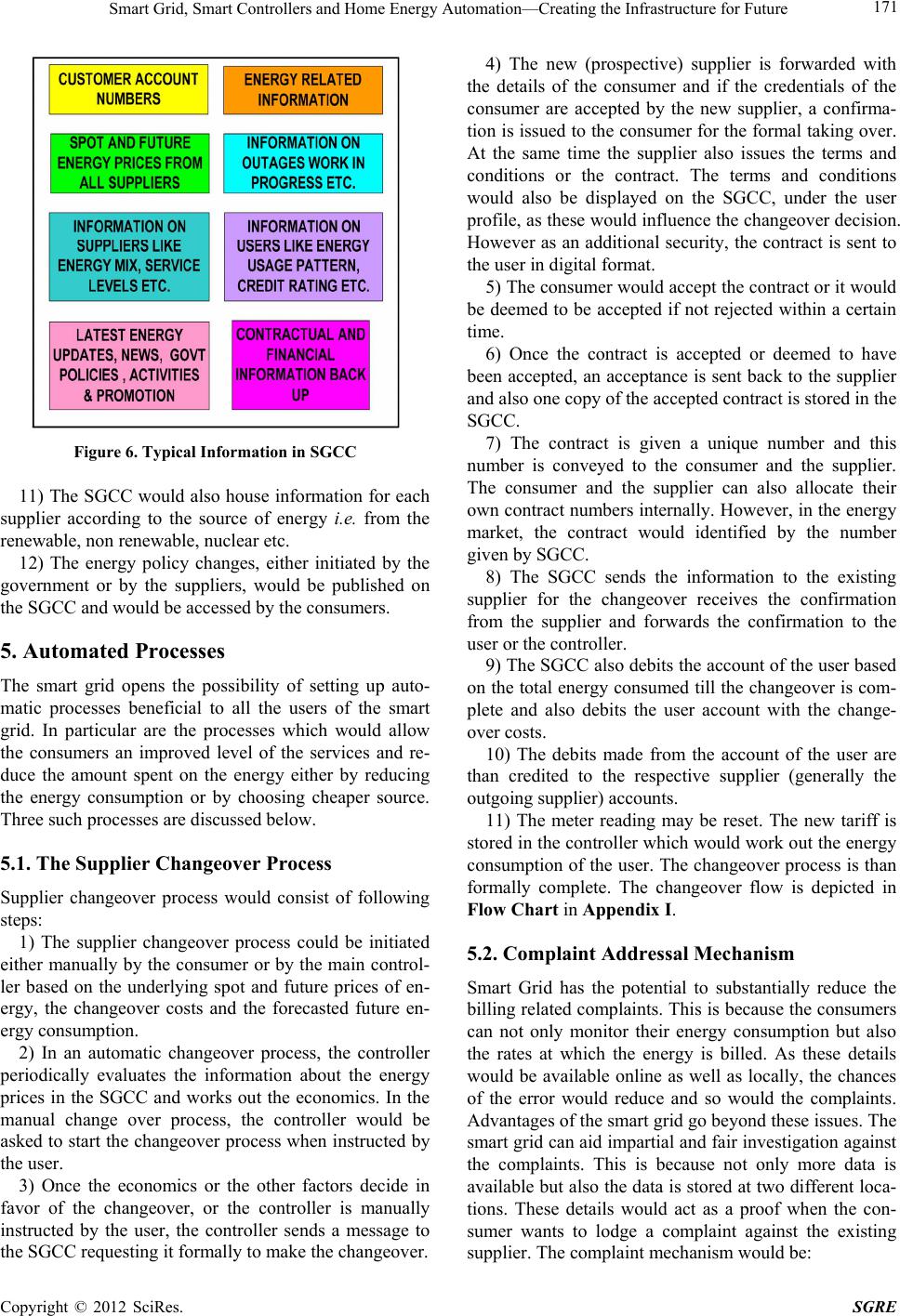 Smart Grid, Smart Controllers and Home Energy Automation—Creating the Infrastructure for Future 171 Figure 6. Typical Information in SGCC 11) The SGCC would also house information for each supplier according to the source of energy i.e. from the renewable, non ren ewable, nuclear etc. 12) The energy policy changes, either initiated by the government or by the suppliers, would be published on the SGCC and would be accessed by the consumers. 5. Automated Processes The smart grid opens the possibility of setting up auto- matic processes beneficial to all the users of the smart grid. In particular are the processes which would allow the consumers an improved level of the services and re- duce the amount spent on the energy either by reducing the energy consumption or by choosing cheaper source. Three such processes are discussed below. 5.1. The Supplier Changeover Process Supplier changeover process would consist of following steps: 1) The supplier changeover process could be initiated either manually by the consumer or by the main control- ler based on the underlying spot and future prices of en- ergy, the changeover costs and the forecasted future en- ergy consumption. 2) In an automatic changeover process, the controller periodically evaluates the information about the energy prices in the SGCC and works out the economics. In the manual change over process, the controller would be asked to start the changeover process when instructed by the user. 3) Once the economics or the other factors decide in favor of the changeover, or the controller is manually instructed by the user, the controller sends a message to the SGCC requesting it formally to make the changeover. 4) The new (prospective) supplier is forwarded with the details of the consumer and if the credentials of the consumer are accepted by the new supplier, a confirma- tion is issued to the consumer for the formal taking over. At the same time the supplier also issues the terms and conditions or the contract. The terms and conditions would also be displayed on the SGCC, under the user profile, as these would influence the changeover decision. However as an additional security, the contract is sent to the user in digital format. 5) The consumer would accept the contract or it would be deemed to be accepted if not rejected within a certain time. 6) Once the contract is accepted or deemed to have been accepted, an acceptance is sent back to the supplier and also one copy of the accepted contract is stored in the SGCC. 7) The contract is given a unique number and this number is conveyed to the consumer and the supplier. The consumer and the supplier can also allocate their own contract numbers internally. However, in the energy market, the contract would identified by the number given by S GCC. 8) The SGCC sends the information to the existing supplier for the changeover receives the confirmation from the supplier and forwards the confirmation to the user or the controller. 9) The SGCC also debits the account of the user based on the total energy consumed till the chang eover is com- plete and also debits the user account with the change- over costs. 10) The debits made from the account of the user are than credited to the respective supplier (generally the outgoing supplier) accounts. 11) The meter reading may be reset. The new tariff is stored in the controller which would work out the energy consumption of the user. The changeover process is than formally complete. The changeover flow is depicted in Flow Chart in Appendix I. 5.2. Complaint Addressal Mechanism Smart Grid has the potential to substantially reduce the billing related complaints. This is because the consumers can not only monitor their energy consumption but also the rates at which the energy is billed. As these details would be available online as well as locally, the chances of the error would reduce and so would the complaints. Advantages of the smart grid go beyond these issues. The smart grid can aid impartial and fair investigation against the complaints. This is because not only more data is available but also the data is sto red at two different loca- tions. These details would act as a proof when the con- sumer wants to lodge a complaint against the existing supplier. The complaint mechanism would be: Copyright © 2012 SciRes. SGRE 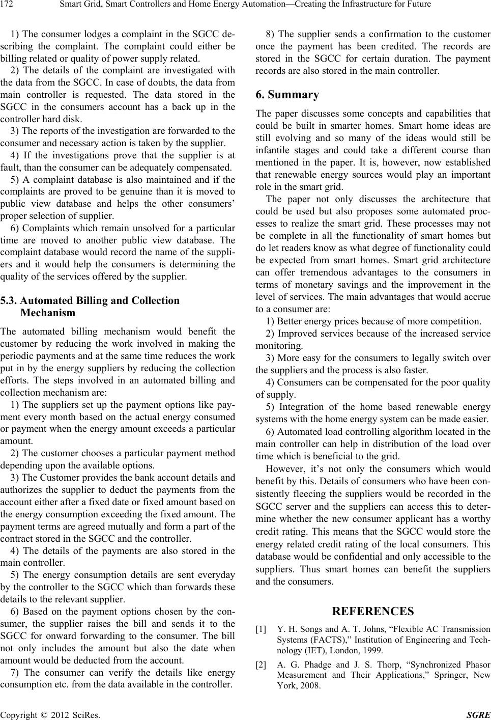 Smart Grid, Smart Controllers and Home Energy Automation—Creating the Infrastructure for Future 172 1) The consumer lodges a complaint in the SGCC de- scribing the complaint. The complaint could either be billing related or quality of power supply related. 2) The details of the complaint are investigated with the data from the SGCC. In case of doubts, the data from main controller is requested. The data stored in the SGCC in the consumers account has a back up in the controll e r hard disk. 3) The reports of the investigation are forwarded to the consumer and necessary action is taken by the supplier. 4) If the investigations prove that the supplier is at fault, than the consumer can be adequately compensated. 5) A complaint database is also maintained and if the complaints are proved to be genuine than it is moved to public view database and helps the other consumers’ proper selection of sup pli e r. 6) Complaints which remain unsolved for a particular time are moved to another public view database. The complaint database would record the name of the suppli- ers and it would help the consumers is determining the quality of the services offered by the supplier. 5.3. Automated Billing and Collection Mechanism The automated billing mechanism would benefit the customer by reducing the work involved in making the periodic payments and at the same time reduces the work put in by the energy suppliers by reducing the collection efforts. The steps involved in an automated billing and collection mechanism are: 1) The suppliers set up the payment options like pay- ment every month based on the actual energy consumed or payment when the energy amount exceeds a particular amount. 2) The customer chooses a particular payment method depending upon the available options. 3) The Customer provides the bank account details and authorizes the supplier to deduct the payments from the account either after a fixed date or fixed amount based on the energy consumption exceeding the fixed amount. The payment terms are agreed mutually and form a part of the contract stored in the SGCC and the controller. 4) The details of the payments are also stored in the main controller. 5) The energy consumption details are sent everyday by the controller to the SGCC which than forwards these details to the relevant supplier. 6) Based on the payment options chosen by the con- sumer, the supplier raises the bill and sends it to the SGCC for onward forwarding to the consumer. The bill not only includes the amount but also the date when amount would be dedu cted from the account. 7) The consumer can verify the details like energy consumption et c. from the data availa bl e in the cont r oll e r. 8) The supplier sends a confirmation to the customer once the payment has been credited. The records are stored in the SGCC for certain duration. The payment records are also stored in the main controller. 6. Summary The paper discusses some concepts and capabilities that could be built in smarter homes. Smart home ideas are still evolving and so many of the ideas would still be infantile stages and could take a different course than mentioned in the paper. It is, however, now established that renewable energy sources would play an important role in the smart grid. The paper not only discusses the architecture that could be used but also proposes some automated proc- esses to realize the smart grid. These processes may not be complete in all the functionality of smart homes but do let readers know as what degree of fun ctiona lity could be expected from smart homes. Smart grid architecture can offer tremendous advantages to the consumers in terms of monetary savings and the improvement in the level of services. The main advantages that would accrue to a consumer are: 1) Better energy prices because of more competition. 2) Improved services because of the increased service monitoring. 3) More easy for the consumers to legally switch over the suppliers and th e pr ocess is also faster. 4) Consumers can be compensated for th e poor quality of supply. 5) Integration of the home based renewable energy systems with the home energy system can be made easier. 6) Automated load con trolling algorithm located in the main controller can help in distribution of the load over time which is beneficial to the grid. However, it’s not only the consumers which would benefit by this. Details of consumers who have been con- sistently fleecing the suppliers would be recorded in the SGCC server and the suppliers can access this to deter- mine whether the new consumer applicant has a worthy credit rating. This means that the SGCC would store the energy related credit rating of the local consumers. This database would be confidential and only accessible to the suppliers. Thus smart homes can benefit the suppliers and the consumers. REFERENCES [1] Y. H. Songs and A. T. Johns, “Flexible AC Transmission Systems (FACTS),” Institution of Engineering and Tech- nology (IET), London, 1999. [2] A. G. Phadge and J. S. Thorp, “Synchronized Phasor Measurement and Their Applications,” Springer, New York, 2008. Copyright © 2012 SciRes. SGRE 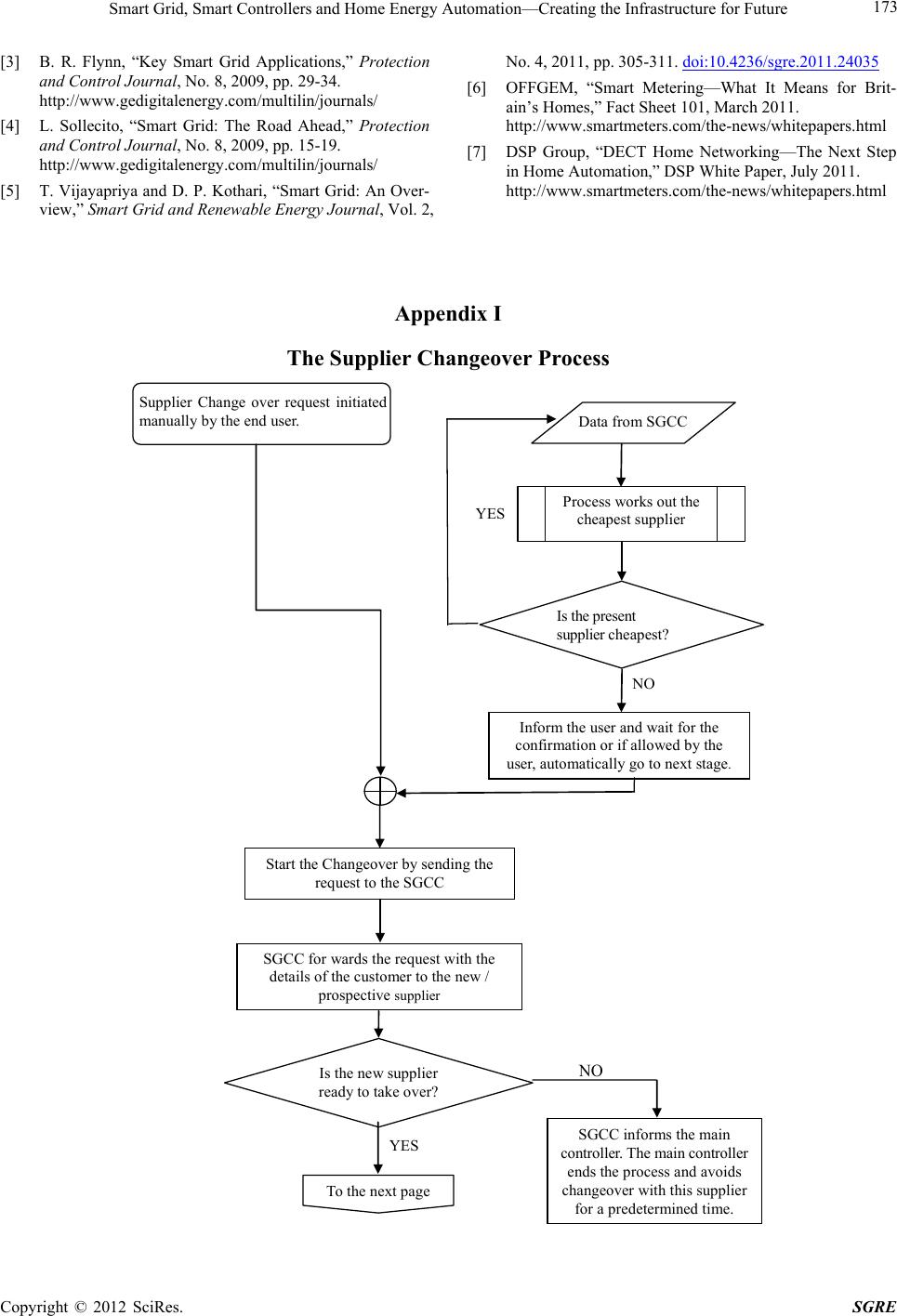 Smart Grid, Smart Controllers and Home Energy Automation—Creating the Infrastructure for Future Copyright © 2012 SciRes. SGRE 173 [3] B. R. Flynn, “Key Smart Grid Applications,” Protection and Control Journal, No. 8, 2009, pp. 29-34. http://www.gedigitalenergy.com/multilin/journals/ [4] L. Sollecito, “Smart Grid: The Road Ahead,” Protection and Control Journal, No. 8, 2009, pp. 15-19. http://www.gedigitalenergy.com/multilin/journals/ [5] T. Vijayapriya and D. P. Kothari, “Smart Grid: An Over- view,” Smart Grid and Renewable Energy Journal, Vol. 2, No. 4, 2011, pp. 305-311. doi:10.4236/sgre.2011.24035 [6] OFFGEM, “Smart Metering—What It Means for Brit- ain’s Homes,” Fact Sheet 101, March 2011. http://www.smartmeters.com/the-news/whitepapers.html [7] DSP Group, “DECT Home Networking—The Next Step in Home Automation,” DSP White Paper, July 2011. http://www.smartmeters.com/the-news/whitepapers.html Appendix I The Supplier Changeover Process Supplier Change over request initiated manually by the end user. Data fro m SGCC Pro cess works out the cheapest supplier Is t he pr es ent supplier che a pe s t? Inform the user and wait for the confirmation or if allowed by the user, auto matically go to next stage . Start the Changeover by sending the req ue st to the SGCC SGCC for wards the request with the details of the customer to the new / prospective supplier To the next page Is the new supplier ready to take over? SGCC informs the main controller. The main controller ends the process and avoids changeover with this supplier for a predetermined time. YES YES N O N O 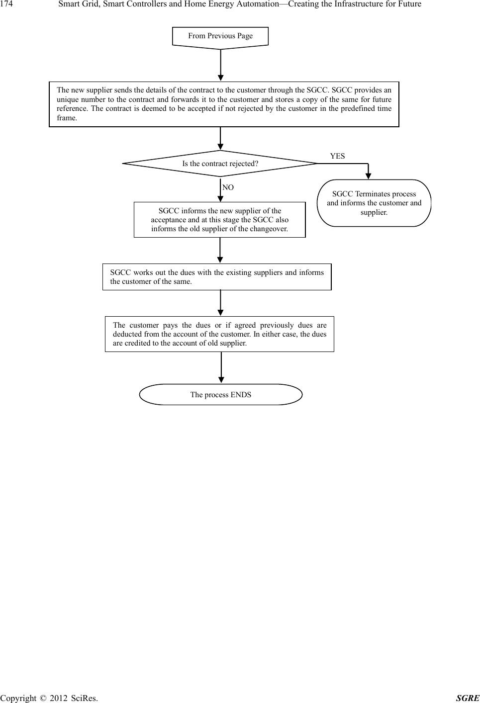 Smart Grid, Smart Controllers and Home Energy Automation—Creating the Infrastructure for Future 174 The new supplier sends the details of the contract to the customer through the SGCC. SGCC provides an uni que number to the cont ract an d forwards i t to th e customer and s tores a cop y of the sa me for fut ure ref erence. Th e cont ract is deemed to be accep ted if not rej ected by t he custom er in the p redefi ned time frame. Is the contract rejected? SGCC in forms t he new suppli er of the acceptance and at this stage the SGCC also informs th e old supplier of th e changeover. SGCC work s out th e dues wit h the existing su pplier s and inform s th e customer of the s ame. The customer pays the dues or if agreed previously dues are ded uct e d from th e acc oun t of the cu stom er. In eith er ca se, th e dues are cr edited to the account of old supplier. The proc ess E N DS SG CC Terminates proce ss and info r ms th e cus tomer and supplier. From Previous Page YES N O Copyright © 2012 SciRes. SGRE |