

Paper Menu >>
Journal Menu >>
 Journal of Minerals and Materials Characterization and Engineering, 2012, 11, 853-857 Published Online August 2012 (http://www.SciRP.org/journal/jmmce) Kinetics Growth and Oxidation Resistance of Aluminide Coatings Deposited by the CVD Method on Re 80 Superalloy Marek Goral, Maciej Pytel, Kamil Dychton, Andrzej Nowotnik Research and Development Laboratory for Aerospace Materials, Rzeszow University of Technology, Rzeszow, Poland Email: [email protected] Received July 2, 2012; revised August 4, 2012; accepted August 19, 2012 ABSTRACT The preliminary results of research on forming the aluminide coatings using CVD method were presented in the article. The coatings were obtained in low activity process on the surface of Rene 80 superalloy. The microstructure analysis and chemical composition analysis were performed applying different values of aluminizing process parameters. The authors present in the article the results of oxidation resistance analysis of aluminide coatings which were obtained on the surface of Rene 80 superalloy using various techniques. It was shown that the coating created during the CVD process was characterized by a good oxidation resistance at the temperature of 1100˚C. Keywords: CVD Aluminizing; Aluminide Coatings; Nickel Superalloy; Re 80 1. Introduction Diffusion aluminizing is one of the basic techniques of protecting the turbine blades surfaces against the oxidiz- ing influence of fumes environment. The pack cementa- tion-, out-of-pack-, slurry- and CVD methods of alumin- izing is one of most commonly used [1,2]. Regardless of the aluminizing technique the mechanism of the coating formation consist in the chemical reaction between the halide containing aluminium and the base material. The β-NiAl phase is created as a result of aluminium diffu- sion. Goward and Boone [3] used pack cementation me- thod and showed two possible courses of growth mecha- nism for aluminide coatings. Using the pack containing 15% of Al, 3% of amonium chloride and 82% of granular Al2O3 it has been observed that the Ni2Al3 phase is cre- ated in the first instance on the surface on the nickel su- peralloy. During this high activity process, the inward aluminium diffusion is the dominant growth mechanism. By using the powder with 15% of Ni2Al3, 3% of NH4Cl and 82% of Al2O3 it has been shown, that β-NiAl is the basic phase constituent. During this low activity process, the outward aluminium diffusion is the dominant growth mechanism. During the high activity process it is neces- sary to perform the additional thermal treatment in order to obtain the transformation of the Ni2Al3 phase into the β-NiAl phase. The out of pack and vapour phase alumin- izing techniques are considered as the extension of pack cementation method. The Al powder and Cr-Al granules are the source of aluminium placed at at least 100 mm away from the coated surface. The process is conducted in the retort furnaces in the atmosphere of argon or hy- drogen. The aluminium fluoride or ammonium fluoride is used as the activating agent [3,4]. It has been proven that there is a possibility of conducting the aluminizing proc- ess of blades cooling channels with a use of out-of-pack method. There is a limitation of parameter control during the aluminizing process using out-of-pack method. It is a result of application of the activating agent introduced in the solid state before the process. The chemical vapour deposition method provides the largest ability of control- ling the parameters values. Sun et al. [5] conducted the aluminizing process with a CVD method applying the flow of AlCl3 and hydrogen which are created in the ex- ternal generator over the powder made of aluminium and aluminum oxide. Howmet company develops the alu- minizing process by chemical vapour deposition [6]. The technological process is conducted as a high or low ac- tivity process, like in the case of pack cementation. Dur- ing the low activity process, the aluminium chloride is created in the external generator by transferring hydrogen chloride through pure aluminium granules. The obtained aluminium chloride was introduced to the retort inside the pit furnace. The Cr-Al were inside the baskets placed around the central pipe which distributed the reactive gas from the external aluminium generator. They were the Copyright © 2012 SciRes. JMMCE 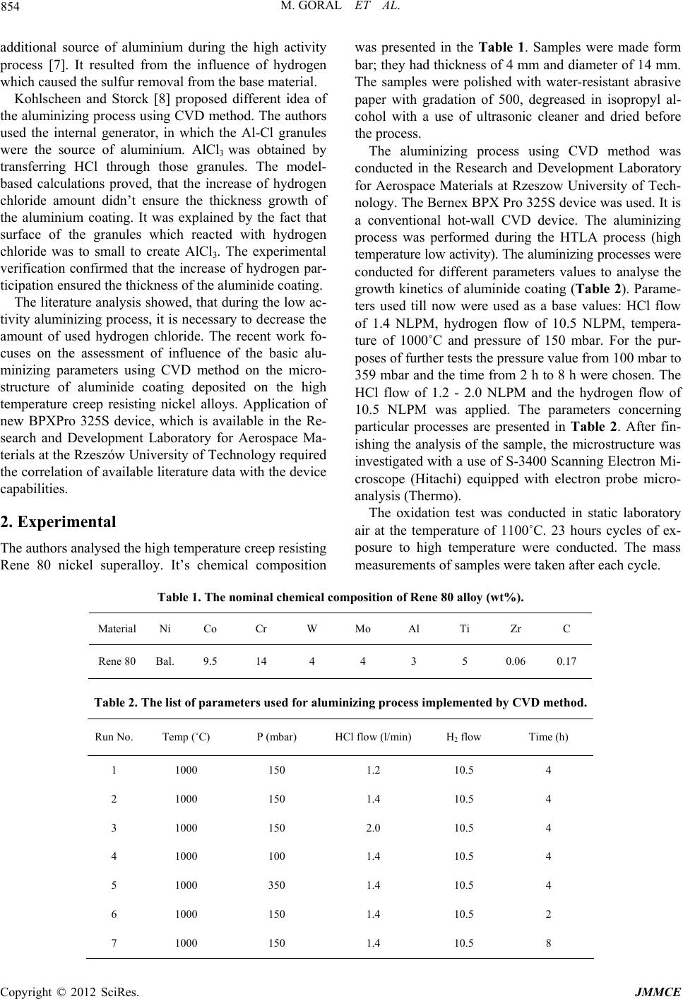 M. GORAL ET AL. 854 additional source of aluminium during the high activity process [7]. It resulted from the influence of hydrogen which caused the sulfur removal from the base material. Kohlscheen and Storck [8] proposed different idea of the aluminizing process using CVD method. The authors used the internal generator, in which the Al-Cl granules were the source of aluminium. AlCl3 was obtained by transferring HCl through those granules. The model- based calculations proved, that the increase of hydrogen chloride amount didn’t ensure the thickness growth of the aluminium coating. It was explained by the fact that surface of the granules which reacted with hydrogen chloride was to small to create AlCl3. The experimental verification confirmed that the increase of hydrogen par- ticipation ensured the thickness of the aluminide coating. The literature analysis showed, that during the low ac- tivity aluminizing process, it is necessary to decrease the amount of used hydrogen chloride. The recent work fo- cuses on the assessment of influence of the basic alu- minizing parameters using CVD method on the micro- structure of aluminide coating deposited on the high temperature creep resisting nickel alloys. Application of new BPXPro 325S device, which is available in the Re- search and Development Laboratory for Aerospace Ma- terials at the Rzeszów University of Technology required the correlation of available literature data with the device capabilities. 2. Experimental The authors analysed the high temperature creep resisting Rene 80 nickel superalloy. It’s chemical composition was presented in the Table 1. Samples were made form bar; they had thickness of 4 mm and diameter of 14 mm. The samples were polished with water-resistant abrasive paper with gradation of 500, degreased in isopropyl al- cohol with a use of ultrasonic cleaner and dried before the process. The aluminizing process using CVD method was conducted in the Research and Development Laboratory for Aerospace Materials at Rzeszow University of Tech- nology. The Bernex BPX Pro 325S device was used. It is a conventional hot-wall CVD device. The aluminizing process was performed during the HTLA process (high temperature low activity). The aluminizing processes were conducted for different parameters values to analyse the growth kinetics of aluminide coating (Table 2). Parame- ters used till now were used as a base values: HCl flow of 1.4 NLPM, hydrogen flow of 10.5 NLPM, tempera- ture of 1000˚C and pressure of 150 mbar. For the pur- poses of further tests the pressure value from 100 mbar to 359 mbar and the time from 2 h to 8 h were chosen. The HCl flow of 1.2 - 2.0 NLPM and the hydrogen flow of 10.5 NLPM was applied. The parameters concerning particular processes are presented in Table 2. After fin- ishing the analysis of the sample, the microstructure was investigated with a use of S-3400 Scanning Electron Mi- croscope (Hitachi) equipped with electron probe micro- analysis (Thermo). The oxidation test was conducted in static laboratory air at the temperature of 1100˚C. 23 hours cycles of ex- posure to high temperature were conducted. The mass measurements of samples were taken after each cycle. Table 1. The nominal chemical composition of Rene 80 alloy (wt%). Material Ni Co Cr W Mo Al Ti Zr C Rene 80 Bal.9.5 14 4 4 3 5 0.06 0.17 Table 2. The list of parameters used for aluminizing process implemented by CVD method. Run No. Temp (˚C) P (mbar) HCl flow (l/min) H2 flow Time (h) 1 1000 150 1.2 10.5 4 2 1000 150 1.4 10.5 4 3 1000 150 2.0 10.5 4 4 1000 100 1.4 10.5 4 5 1000 350 1.4 10.5 4 6 1000 150 1.4 10.5 2 7 1000 150 1.4 10.5 8 Copyright © 2012 SciRes. JMMCE 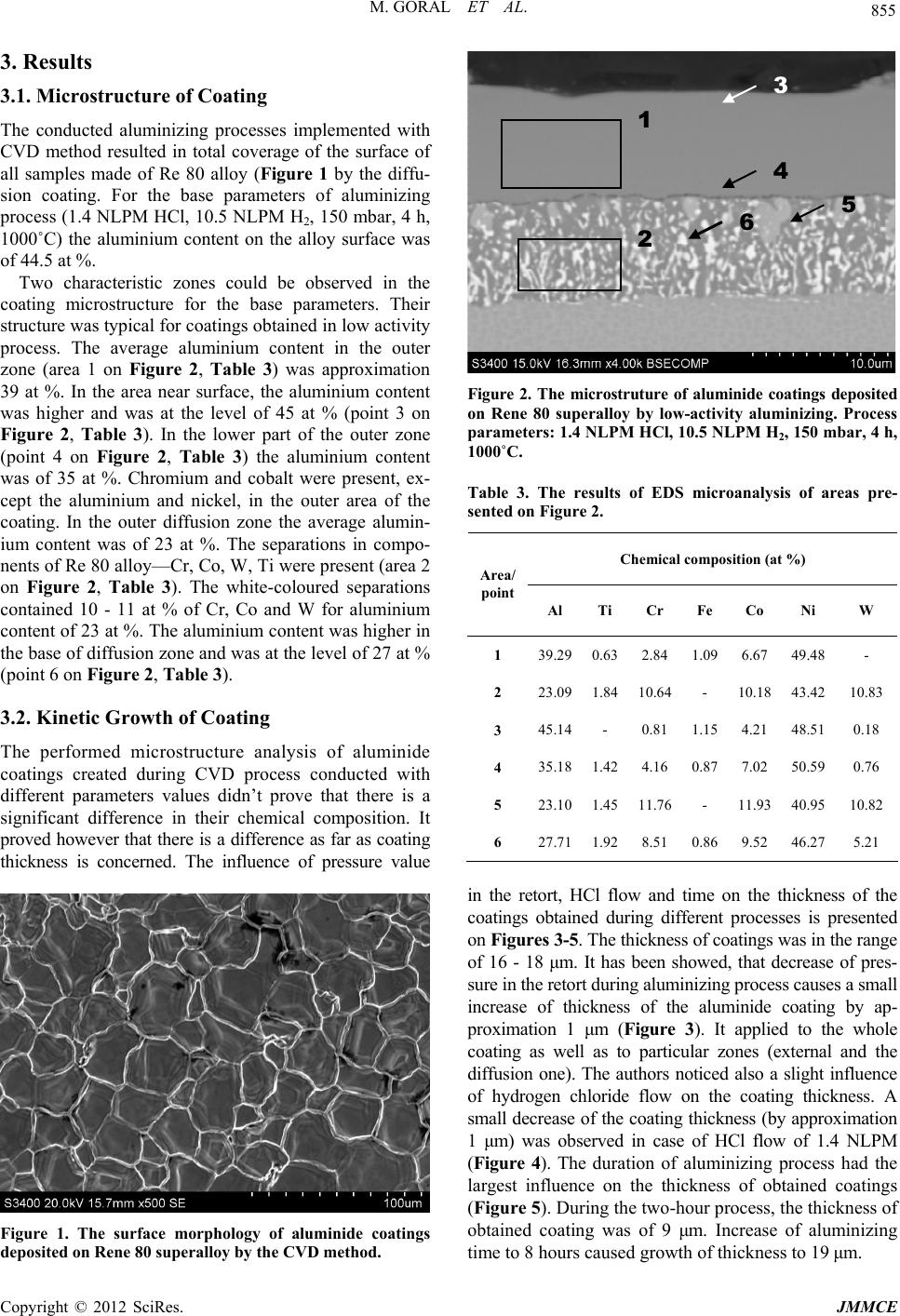 M. GORAL ET AL. 855 3. Results 3 3.1. Microstructure of Coating 1 The conducted aluminizing processes implemented with CVD method resulted in total coverage of the surface of all samples made of Re 80 alloy (Figure 1 by the diffu- sion coating. For the base parameters of aluminizing process (1.4 NLPM HCl, 10.5 NLPM H2, 150 mbar, 4 h, 1000˚C) the aluminium content on the alloy surface was of 44.5 at %. 4 5 6 2 Two characteristic zones could be observed in the coating microstructure for the base parameters. Their structure was typical for coatings obtained in low activity process. The average aluminium content in the outer zone (area 1 on Figure 2, Table 3) was approximation 39 at %. In the area near surface, the aluminium content was higher and was at the level of 45 at % (point 3 on Figure 2, Table 3). In the lower part of the outer zone (point 4 on Figure 2, Table 3) the aluminium content was of 35 at %. Chromium and cobalt were present, ex- cept the aluminium and nickel, in the outer area of the coating. In the outer diffusion zone the average alumin- ium content was of 23 at %. The separations in compo- nents of Re 80 alloy—Cr, Co, W, Ti were present (area 2 on Figure 2, Table 3). The white-coloured separations contained 10 - 11 at % of Cr, Co and W for aluminium content of 23 at %. The aluminium content was higher in the base of diffusion zone and was at the level of 27 at % (point 6 on Figure 2, Table 3). 3.2. Kinetic Growth of Coating The performed microstructure analysis of aluminide coatings created during CVD process conducted with different parameters values didn’t prove that there is a significant difference in their chemical composition. It proved however that there is a difference as far as coating thickness is concerned. The influence of pressure value Figure 1. The surface morphology of aluminide coatings deposited on Rene 80 superalloy by the CVD method. Figure 2. The microstruture of aluminide coatings deposited on Rene 80 superalloy by low-activity aluminizing. Process parameters: 1.4 NLPM HCl, 10.5 NLPM H2, 150 mbar, 4 h, 1000˚C. Table 3. The results of EDS microanalysis of areas pre- sented on Figure 2. Chemical composition (at %) Area/ point Al Ti Cr Fe Co Ni W 1 39.290.63 2.84 1.09 6.67 49.48- 2 23.091.8410.64 - 10.18 43.4210.83 3 45.14- 0.81 1.15 4.21 48.510.18 4 35.181.42 4.16 0.87 7.02 50.590.76 5 23.101.4511.76 - 11.93 40.9510.82 6 27.711.92 8.51 0.86 9.52 46.275.21 in the retort, HCl flow and time on the thickness of the coatings obtained during different processes is presented on Figures 3-5. The thickness of coatings was in the range of 16 - 18 μm. It has been showed, that decrease of pres- sure in the retort during aluminizing process causes a small increase of thickness of the aluminide coating by ap- proximation 1 μm (Figure 3). It applied to the whole coating as well as to particular zones (external and the diffusion one). The authors noticed also a slight influence of hydrogen chloride flow on the coating thickness. A small decrease of the coating thickness (by approximation 1 μm) was observed in case of HCl flow of 1.4 NLPM (Figure 4). The duration of aluminizing process had the largest influence on the thickness of obtained coatings (Figure 5). During the two-hour process, the thickness of obtained coating was of 9 μm. Increase of aluminizing time to 8 hours caused growth of thickness to 19 μm. Copyright © 2012 SciRes. JMMCE 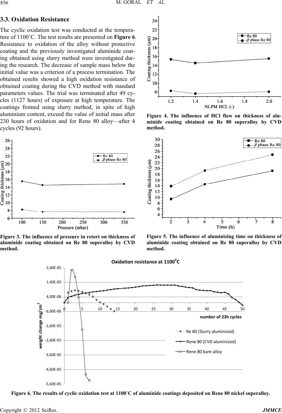 M. GORAL ET AL. 856 3.3. Oxidation Resistance The cyclic oxidation test was conducted at the tempera- ture of 1100˚C. The test results are presented on Figure 6. Resistance to oxidation of the alloy without protective coating and the previously investigated aluminide coat- ing obtained using slurry method were investigated dur- ing the research. The decrease of sample mass below the initial value was a criterion of a process termination. The obtained results showed a high oxidation resistance of obtained coating during the CVD method with standard parameters values. The trial was terminated after 49 cy- cles (1127 hours) of exposure at high temperature. The coatings fromed using slurry method, in spite of high aluminium content, exceed the value of initial mass after 230 hours of oxidation and for Rene 80 alloy—after 4 cycles (92 hours). Figure 3. The influence of pressure in retort on thickness of aluminide coating obtained on Re 80 superalloy by CVD method. Figure 4. The influence of HCl flow on thickness of alu- minide coating obtained on Re 80 superalloy by CVD method. Figure 5. The influence of aluminizing time on thickness of aluminide coating obtained on Re 80 superalloy by CVD method. Oxidationresistanceat1100 o C ‐4,60E‐05 ‐3,60E‐05 ‐2,60E‐05 ‐1,60E‐05 ‐6,00E‐06 4,00E‐06 1,40E‐05 2,40E‐05 0510 15 20 25 30 35 40 45 50 numberof23hcycles weightchangemg/cm 2 ‐5,60E‐05 Re80(Slurryaluminized) Rene80(CVDaluminized) Rene80barealloy Figure 6. The results of cyclic oxidation test at 1100˚C of aluminide coatings deposited on Rene 80 nickel superalloy. Copyright © 2012 SciRes. JMMCE  M. GORAL ET AL. 857 4. Summary The CVD method is one of most modern techniques of aluminizing of turbine blades in aircraft engines. The conducted technological trials made with BPX Pro 325S device showed a possibility of creating the aluminide coatings with a structure typical for low activity process. The coating consisted of the outer layer (β-NiAl phase) containing approximation 45 at % of aluminium and the transition diffusion zone. The coating structure indicates the growth resulting from outward nickel diffusion. The analysis of coating growth kinetics didn’t show the sig- nificant influence of pressure in the retort and the HCl flow on the thickness of formed coating. It is necessary to change a value of hydrogen chloride flow in order to increase the coating thickness. The conducted research proved that the aluminizing using CVD method is an efficient way of surface protec- tion against oxidation for Rene 80 alloy. It was con- firmed by the result of cyclic oxidation test. High heat resistance of the coating obtained with CVD method can be a result of application of the hydrogen atmosphere. The method provides high quality of obtained coating [7]. 5. Acknowledgements The research was supported by National Centre for Re- search and Development under grant No. PR NR15- 0121-10/2011. REFERENCES [1] G. W. Goward, “Progress in Coatings for Gas Turbine Airfoils,” Surface and Coatings Technology, Vol. 108-109, 1998, pp. 73-79. doi:10.1016/S0257-8972(98)00667-7 [2] M. J. Pomeroy, “Coatings for Gas Turbine Materials and Long Term Stability Issues,” Materials & Design, Vol. 26, No. 3, 2005, pp. 223-231. doi:10.1016/j.matdes.2004.02.005 [3] G. W. Goward and D. H. Boone, “Mechanisms of Forma- tion of Diffusion Aluminide Coatings on Nickel-Base Superalloys,” Oxidation of Metals, Vol. 3, No. 5, 1971, pp. 475-495. doi:10.1007/BF00604047 [4] A. Squillace, R. Bonetti, N. J. Archer and J. A. Yeatman, “The Control of the Composition and Structure of Alu- minide Layers Formed by Vapour Aluminising,” Surface and Coatings Technology, Vol. 120-121, 1999, pp. 118- 123. doi:10.1016/S0257-8972(99)00347-3 [5] W.-P. Sun, H. J. Lin and M.-H. Hon, “CVD Aluminide Nickel,” Metallurgical and Materials Transactions A, Vol. 17, No. 2, 1986, pp. 215-220. [6] B. M. Warnes, A. L. Purvis and D. L. Near, “Chemical Vapor Deposition Apparatus and Method,” United States Patent No. US 6793966 B2, 2004. [7] B. M. Warnes and D. C. Punola, “Clean Diffusion Coat- ings by Chemical Vapour Deposition,” Surface and Coat- ings Technology, Vol. 94-95, 1997, pp. 1-6. doi:10.1016/S0257-8972(97)00467-2 [8] J. Kohlscheen and H. R. Stock, “Gas Phase Aluminizing of Nickel Alloys with Hydrogen Chloride,” Surface and Coatings Technology, Vol. 202, No. 4-7, 2007, pp. 613- 616. doi:10.1016/j.surfcoat.2007.07.003 Copyright © 2012 SciRes. JMMCE |