

Paper Menu >>
Journal Menu >>
 Journal of Minerals and Materials Characterization and Engineering, 2012, 11, 785-789 Published Online August 2012 (http://www.SciRP.org/journal/jmmce) Drilling of TiO2 and ZnS Filled GFRP Composites K. V. Arun1*, D. Sujay Kumar2, M. C. Murugesh3 1Department of Mechanical Engineering, Government Engineering College, Haveri, India 2Department of Studies in Industrial and Production Engineering, University B.D.T. College of Engineering, Davangere, India 3Department of Mechanical Engineering, Gowdara Mallikarjunappa Institute of Technology, Davangere, India Email: *[email protected] Received March 13, 2012; revised April 30, 2012; accepted May 21, 2012 ABSTRACT In the present work an attempt has been made in order to investigate the drilling behavior of the TiO2 and ZnS filled glass fabric reinforced polymer matrix composites (GFRP). Th e volume fractions in the matrix were chosen as 1%, 2% and 3%. Drilling has been con ducted on a rad ial drilling machin e. Speed of drilling and drill tool d iameter were consid- ered as the varying parameters with three levels. Thrust force has been considered as the output parameter and is been measured in each combination of parameters chosen. Results reveal that, the addition of filler will increase the thrust force developed during drilling, also results indicate that, addition of filler will increase thrust force upto 2 vol% of filler thereafter increase in filler content result in almost constant thrust developed. Also it can be observed that, with the increase in drill tool diameter the thrust developed also in creases. Keywords: Fillers; Thrust Force; Drilling; GFRP; Speed 1. Introduction Polymer matrix composites are increasingly being used because of their high stiffness, specific strength and wear resistance. On account of their good combinations of properties, fiber reinforced polymer composites are used particularly in the automotive, aircraft industries and the manufacture of spaceships and sea vehicles [1]. It is gen- erally known that the epoxy resins with appropriate cur- ing agents find use as products in protective coatings, adhesives, structural components because of their good mechanical properties, excellent chemical resistance, good wettability and electrical characteristics [2]. Their use is always indicated where fluids are ineffective or cannot be tolerated because of the possibility of con- tamination of the product or the environment, or the lack of opportunity for maintenance [3]. Many researchers [4-7] were reported that the wear behavior of polymers was improved by the incorporation solid particles. The filler materials include organic, inor- ganic and mechanical particulate materials. The addition of filler particles to polymer matrices can produce a number of desirable effects, and this has been widely been investigated in the past decades. Among polymers, epoxy resin is widely used in production of glass fiber composites due to their wetting power and adhesion to glass fiber, low setting shrinkage, considerable cohesion strength, adequate dielectric characteristics, and thermal properties. Epoxies commonly modified by the inclusion of inorganic-particulate fillers, such as silica, alumina, mica or talc. Fillers are added to improv e fracture tough- ness and electrical or heat transfer properties, to increase resin stiffness, wear resistance, and to reduce the coeffi- cient of thermal expansion [8]. Drilling of composite materials irresp ective of the area of application can be considered as a critical operation owing to their tendency to delaminate when subjected to mechanical stresses. With regard to the quality of ma- chined component, the principal drawbacks are related to surface delamination, fibre/resin pullout and inadequate surface roughness of the hole wall. Among the defects caused by drilling, delamination appears to be the most critical. In order to overcome these difficulties it is nec- essary to develop procedur es to select appropriate cutting parameters, due to the fact that an unsuitable choice could lead to unacceptable work material degradation. The variation of cutting forces with or without onset damage during drilling was investigated [9] and con- cluded that a damage-free drilling process may be ob- tained by the proper selections of tool geometry and cut- ting parameters. The influence of trepanning tool on thrust force and torque when drilling GFRP has been investigated [10]. The investigation showed that the per- formance of the trepanning tool was superior to the con- ventional twist drill, resulting in 50 and 10% of thrust force and torque, respectively. In order to investigate the effect of the drill diameter on the thrust force and torqu e, *Corresponding author. Copyright © 2012 SciRes. JMMCE 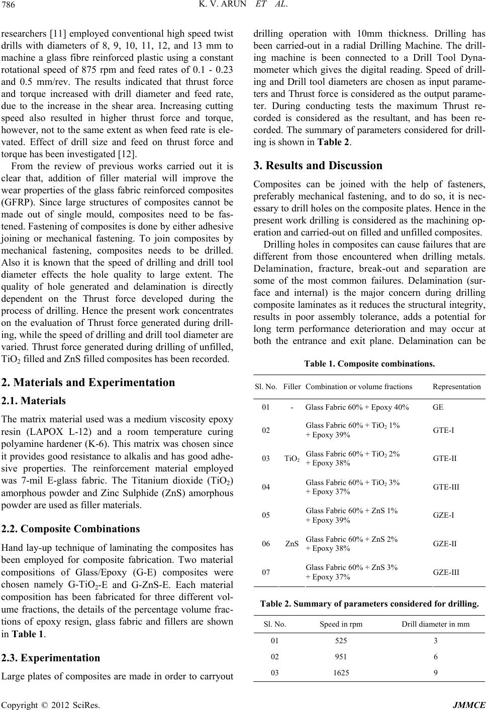 K. V. ARUN ET AL. 786 researchers [11] employed conventional high speed twist drills with diameters of 8, 9, 10, 11, 12, and 13 mm to machine a glass fibre reinforced plastic using a constant rotational speed of 875 rpm and feed rates of 0.1 - 0.23 and 0.5 mm/rev. The results indicated that thrust force and torque increased with drill diameter and feed rate, due to the increase in the shear area. Increasing cutting speed also resulted in higher thrust force and torque, however, not to th e same extent as when feed rate is ele- vated. Effect of drill size and feed on thrust force and torque has been investigated [12]. From the review of previous works carried out it is clear that, addition of filler material will improve the wear properties of the glass fabric reinforced composites (GFRP). Since large structures of composites cannot be made out of single mould, composites need to be fas- tened. Fastening of composites is done by either adhesive joining or mechanical fastening. To join composites by mechanical fastening, composites needs to be drilled. Also it is known that the speed of drilling and drill tool diameter effects the hole quality to large extent. The quality of hole generated and delamination is directly dependent on the Thrust force developed during the process of drilling. Hence the present work concentrates on the evaluation of Thrust force generated during drill- ing, while the speed of drilling and drill tool diameter are varied. Thrust force gen erated during drilling of unfilled, TiO2 filled and ZnS filled composites has been recorded. 2. Materials and Experimentation 2.1. Materials The matrix material used was a medium viscosity epoxy resin (LAPOX L-12) and a room temperature curing polyamine hardener (K-6). This matrix was chosen since it provides good resistance to alkalis and has good adhe- sive properties. The reinforcement material employed was 7-mil E-glass fabric. The Titanium dioxide (TiO2) amorphous powder and Zinc Sulphide (ZnS) amorphous powder are used as filler materials. 2.2. Composite Combinations Hand lay-up technique of laminating the composites has been employed for composite fabrication. Two material compositions of Glass/Epoxy (G-E) composites were chosen namely G-TiO2-E and G-ZnS-E. Each material composition has been fabricated for three different vol- ume fractions, the details of the percentage volume frac- tions of epoxy resign, glass fabric and fillers are shown in Table 1. 2.3. Experimentation Large plates of composites are made in order to carryout drilling operation with 10mm thickness. Drilling has been carried-out in a radial Drilling Machine. The drill- ing machine is been connected to a Drill Tool Dyna- mometer which gives the digital reading. Speed of drill- ing and Drill tool diameters are chosen as input parame- ters and Thr ust force is con sidered as the outpu t parame- ter. During conducting tests the maximum Thrust re- corded is considered as the resultant, and has been re- corded. The summary of parameters considered for drill- ing is shown in Table 2. 3. Results and Discussion Composites can be joined with the help of fasteners, preferably mechanical fastening, and to do so, it is nec- essary to drill holes on the composite plates. Hence in the present work drilling is considered as the machining op- eration and carried-out on filled and unfilled composites. Drilling holes in composites can cause failures that are different from those encountered when drilling metals. Delamination, fracture, break-out and separation are some of the most common failures. Delamination (sur- face and internal) is the major concern during drilling composite laminates as it reduces the structu ral integrity, results in poor assembly tolerance, adds a potential for long term performance deterioration and may occur at both the entrance and exit plane. Delamination can be Table 1. Composite combinations. Sl. No.FillerCombination or volume fractions Representation 01 - Glass Fabric 60% + E poxy 40% GE 02 Glass Fabric 60% + TiO2 1% + Epoxy 39% GTE-I 03 Glass Fabric 60% + TiO2 2% + Epoxy 38% GTE-II 04 TiO2 Glass Fabric 60% + TiO2 3% + Epoxy 37% GTE-III 05 Glass Fabric 60% + ZnS 1% + Epoxy 39% GZE-I 06 Glass Fabric 60% + ZnS 2% + Epoxy 38% GZE-II 07 ZnS Glass Fabric 60% + ZnS 3% + Epoxy 37% GZE-III Table 2. Summary of parameters considered for drilling. Sl. No. Speed in rpm Drill diameter in mm 01 525 3 02 951 6 03 1625 9 Copyright © 2012 SciRes. JMMCE 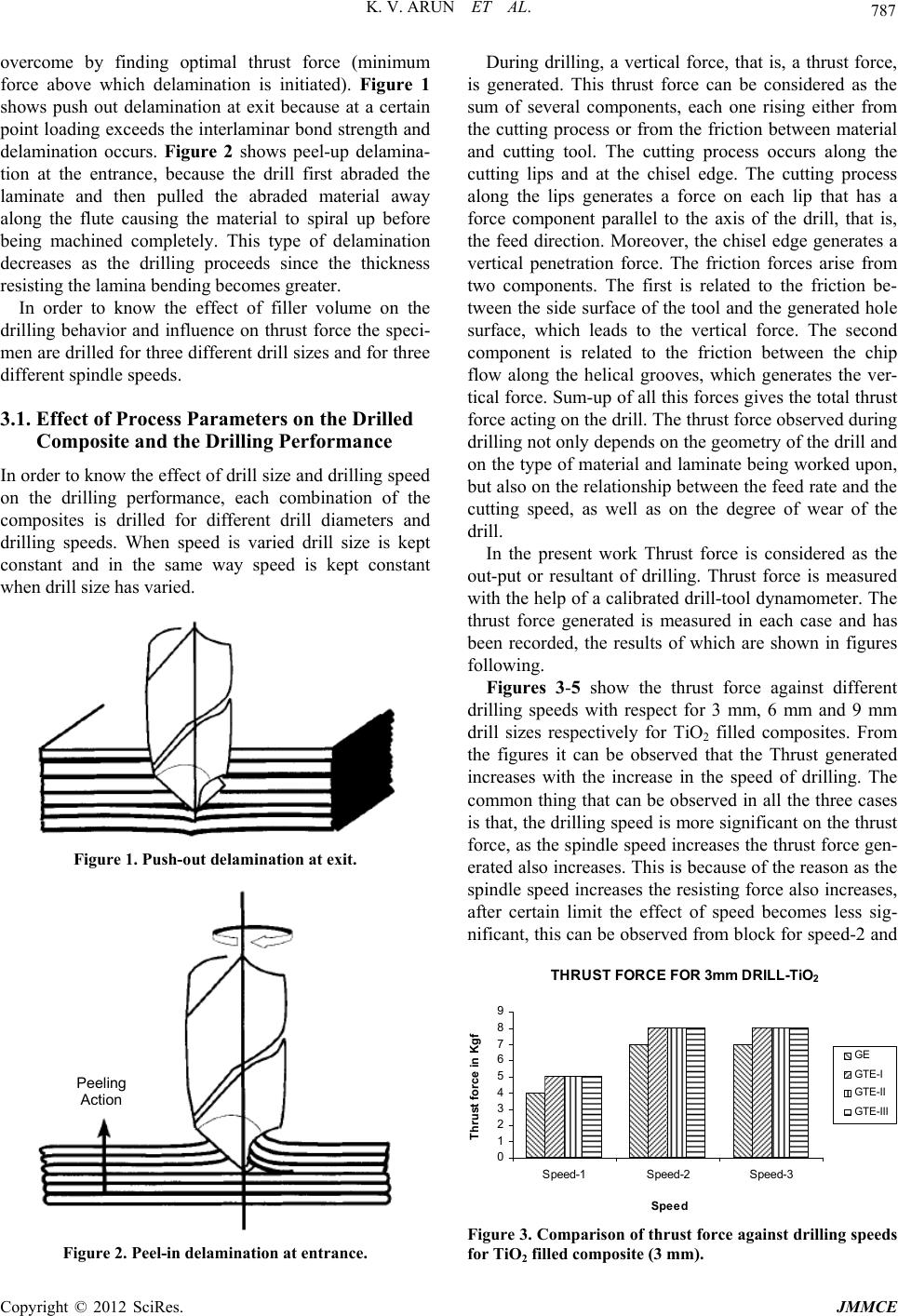 K. V. ARUN ET AL. 787 overcome by finding optimal thrust force (minimum force above which delamination is initiated). Figure 1 shows push out delamination at exit because at a certain point loading exceeds the interlaminar bond strength and delamination occurs. Figure 2 shows peel-up delamina- tion at the entrance, because the drill first abraded the laminate and then pulled the abraded material away along the flute causing the material to spiral up before being machined completely. This type of delamination decreases as the drilling proceeds since the thickness resisting the lamina bending becom es greater. In order to know the effect of filler volume on the drilling behavior and influence on thrust force the speci- men are drilled for three different drill sizes and for three different spindle speeds. 3.1. Effect of Process Parameters on the Drilled Composite and the Drilling Performance In order to know the effect of drill size and drilling speed on the drilling performance, each combination of the composites is drilled for different drill diameters and drilling speeds. When speed is varied drill size is kept constant and in the same way speed is kept constant when drill size has varied. Figure 1. Push-out delamination at exit. Peeling Action Figure 2. Peel-in delamina tion at entran ce. During drilling, a vertical force, that is, a thrust force, is generated. This thrust force can be considered as the sum of several components, each one rising either from the cutting process or from the friction between material and cutting tool. The cutting process occurs along the cutting lips and at the chisel edge. The cutting process along the lips generates a force on each lip that has a force component parallel to the axis of the drill, that is, the feed direction. Moreover, the chisel edge generates a vertical penetration force. The friction forces arise from two components. The first is related to the friction be- tween the side surface of the tool and the generated hole surface, which leads to the vertical force. The second component is related to the friction between the chip flow along the helical grooves, which generates the ver- tical force. Sum-up of all this forces gives the total thrust force acting on the d rill. Th e thru st force ob served du ring drilling no t only d epend s on th e geometry of the d rill and on the type of material and laminate be ing worked upon, but also on the relation ship between the feed rate and the cutting speed, as well as on the degree of wear of the drill. In the present work Thrust force is considered as the out-put or resultant of drilling. Thrust force is measured with the help of a calibrated drill-tool d ynamometer. The thrust force generated is measured in each case and has been recorded, the results of which are shown in figures following. Figures 3-5 show the thrust force against different drilling speeds with respect for 3 mm, 6 mm and 9 mm drill sizes respectively for TiO2 filled composites. From the figures it can be observed that the Thrust generated increases with the increase in the speed of drilling. The common thing that can be observed in all the three cases is that, the drilling speed is more significan t on the thrust force, as the spindle speed increases the thrust force gen- erated also increases. This is because of the reason as the spindle speed increases the resisting force also increases, after certain limit the effect of speed becomes less sig- nificant, this can be observed from block for speed-2 and THRUST FORCE FO R 3m m DRI LL-TiO 2 0 1 2 3 4 5 6 7 8 9 Speed-1Speed-2 Speed-3 Speed Thrust force in Kgf GE GTE- I GTE- II GTE- III Figure 3. Comparison of thrust force against drilling speeds for TiO2 filled composite (3 mm). Copyright © 2012 SciRes. JMMCE 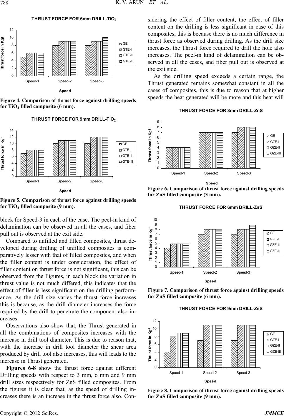 K. V. ARUN ET AL. 788 THRUST F O RCE F O R 6 m m DRIL L 0 2 4 6 8 10 12 Speed-1Speed-2 Speed-3 Spee d Thr u st for ce in Kgf -TiO 2 GE GTE -I GTE -II GTE -III Figure 4. Comparison of thrust force against drilling speeds for TiO2 filled composite (6 mm). THRUST FO RCE FOR 9mm DRIL 0 2 4 6 8 10 12 14 Speed-1 Speed-2 Speed-3 Speed Thrust force in Kgf L-TiO 2 GE GTE-I GTE-II GTE- III Figure 5. Comparison of thrust force against drilling speeds for TiO2 filled composite (9 mm). block for Speed-3 in each of the case. The peel-in kind of delamination can be observed in all the cases, and fiber pull out is observed at the exit side. Compared to unfilled and filled composites, thrust de- veloped during drilling of unfilled composites is com- paratively lesser with that of filled composites, and wh en the filler content is under consideration, the effect of filler content on thrust force is not significan t, this can be observed from the Figures, in each block the variation in thrust value is not much differed, this indicates that the effect of filler is less significant on the drilling perform- ance. As the drill size varies the thrust force increases this is because, as the drill diameter increases the force required by the drill to penetrate the component also in- creases. Observations also show that, the Thrust generated in all the combinations of composites increases with the increase in drill tool diameter. This is due to reason that, with the increase in drill tool diameter the shear area produced by drill too l also in creases, this will leads to th e increase in Thrust generated. Figures 6-8 show the thrust force against different Drilling speeds with respect to 3 mm, 6 mm and 9 mm drill sizes respectively for ZnS filled composites. From the figures it is clear that, as the speed of drilling in- sidering the effect of filler content, the effect of filler content on the drilling is less significant in case of this composites, this is because there is no much difference in thrust force as observed during drilling. As the drill size increases, the Thrust force required to drill the hole also increases. The peel-in kind of delamination can be ob- served in all the cases, and fiber pull out is observed at the exit side. As the dri creases there is an increase in the thrust force also. Con- lling speed exceeds a certain range, the Thrust generated remains somewhat constant in all the cases of composites, this is due to reason that at higher speeds the heat generated will be more and this heat will THRUST F ORCE FOR 3 mm DRIL L - ZnS 0 1 2 3 4 5 6 7 8 9 Speed-1 Speed-2 Speed-3 Spee d Thrust force in Kgf GE GZE- I GZE- II GZE- III Figure 6. Comparison of thrust force against drilling speeds for ZnS filled composite (3 mm). THRUST FO RCE FO R 6mm DRI LL-ZnS 0 1 2 3 4 5 6 7 8 9 10 Speed-1Speed-2 Speed-3 Speed Thru st force in Kgf GE GZE-I GZE-II GZE- III Figure 7. Comparison of thrust force against drilling speeds for ZnS filled composite (6 mm). THRUST F ORCE FOR 9mm DRILL- ZnS 0 2 4 6 8 10 12 Speed-1Speed-2 Speed-3 Spee d Thrust force in Kgf GE GZE- I GZE- II GZE - III Figure 8. Comparison of thrust force against drilling speeds for ZnS filled composite (9 mm). Copyright © 2012 SciRes. JMMCE  K. V. ARUN ET AL. Copyright © 2012 SciRes. JMMCE 789 ntation conducted and observations REFERENCES [1] H. Pihtili andn of the Wear Be- haviour of a Gomposite and make the material behave softer that the usual case and hence the resistance offered for drilling becomes lesser, this will result in development of less Thrust. In com- parison with TiO2 and ZnS filled composites, TiO2 filled composites will offer more resistance that ZnS filled composites. Since the ZnS filled composites are com- paratively less brittle that TiO2 filled composites, they behaves bit softer at early stages than TiO2 filled com- posites, offering less oppositio n for drilling. 4. Conclusions From the experime made during testing, following conclusion can be drawn: The thrust force generated during drilling of filled composites mainly depends upon drill diameter and the speed of drilling in the present case. Effect of filler volume on the Thrust generated is neglizable. Thrust force developed during drilling of TiO2 filled composites is more in comparison with ZnS filled composites. N. Tosun, “Investigatio lass-Fibre-Reinforced C Plain Polyester Resin,” Composites Science and Technology, Vol. 62, No. 3, 2002, pp. 367-370. doi:10.1016/S0266-3538(01)00196-8 [2] Kishore, P. Sampathkumaran, S. See theya, A. Murali and R. K. Kumar, “tharamu, S. Vyna- SEM Observations ology International, Vol. 22, No. 2, 1989, pp. 103- of the Effects of Velocity and Load on the Sliding Wear Characteristics of Glass Fabric-Epoxy Composites with Different Fillers,” Wear, Vol. 237, No. 1, 2000, pp. 20- 27. [3] E. Santer and H. Czinchos, “Tribology of Polymers,” Trib 109. doi:10.1016/0301-679X(89)90170-9 [4] J. Bijwe and J. Indumathi, “Influence of Fibers and Solid . Sınmazcelik, “Erosive Wear Behaviour of Lubricants on Low Amplitude Oscillating Wear of Poly- etherimide Composites,” Wear, Vol. 257, No. 5-6, 2004, pp. 562-572. [5] N. Sarı and T Carbon Fibre/Polyetherimide Composites under Low Par- ticle Speed,” Materials & Design, Vol. 28, No. 1, 2007, pp. 351-355. doi:10.1016/j.matdes.2005.05.014 [6] P. Samyn, J. Quintelier, W. Ost, P. De Baets and G. Schoukens, “Sliding Behaviour of Pure Polyester and Polyester-PTFE Filled Bulk Composites in Overload Conditions,” Polymer Testing, Vol. 24, No. 5, 2005, pp. 588-603. doi:10.1016/j.polymertesting.2005.02.012 [7] J. Bijwe, J. J. Rajesh, A. Jeyakumar, A. Ghosh and U. S. Tewari, “Influence of Solid Lubricants and Fibre Rein- forcement on Wear Behaviour of Polyethersulphone,” Tribology International, Vol. 33, No. 10, 2000, pp. 697- 706. doi:10.1016/S0301-679X(00)00104-3 [8] L. M. McGrath, R. S. Parnas, S. H. King, J. L. Schroeder, D. A. Fischer and J. L. Lenhart, “Investigation of the Thermal, Mechanical and Fracture Properties of Alumina- Epoxy Composites,” Polymer, Vol. 49, No. 4, 2008, pp. 999-1014. doi:10.1016/j.polymer.2007.12.014 [9] W. Chen, “Some Expe riment al Investigations in the Drill- - and T. Machaly, “Factors Mohan, A. Ramachandra, S. M. Kulkarni, “Ma- ing of Carbon Fiber Reinforced Plastic (CFRP) Compos- ite Laminates,” International Journal of Machine Tools and Manufacture, Vol. 37, No. 8, 1997, pp. 1097-1108. [10] J. Mathew, N. Ramakrishnan and N. K. Naik, “Investiga tions into the Effect of Geometry of a Trepanning Tool on Thrust and Torque during Drilling of GFRP Composites,” Journal of Materials Processing Technology, Vol. 91, No. 1-3, 1999, pp. 1-11. [11] I. El-Sonbaty, U. A. Khashaba Affecting the Machinability of GFR/Epoxy Composites,” Composite Structures, Vol. 63, No. 3-4, 2004, pp. 329- 338. [12] N. S. chining of Fiber-Reinforced Thermoplastics: Influence of Feed and Drill Size on Thrust Force and Torque during Drilling,” Journal of Reinforced Plastics & Composites, Vol. 24, No. 12, 2005, pp. 1247-1257. |