

Paper Menu >>
Journal Menu >>
 World Journal of Nano Science and Engineering, 2012, 2, 110-115 http://dx.doi.org/10.4236/wjnse.2012.22014 Published Online June 2012 (http://www.SciRP.org/journal/wjnse) Formation of Photosensitizing Crystalline C60 Particles by Ink-Jet Method Masahito Ban, Fusako Sasaki Systems Engineering Major, Graduate School, Nippon Institute of Technology, Saitama, Japan Email: [email protected] Received March 26, 2012; revised April 24, 2012; accepted May 8, 2012 ABSTRACT The crystalline fullerene C60 particles were formed and immobilized on poly(dimethylsiloxane) (PDMS) substrates un- der the various discharge conditions by an ink-jet method, and investigated for the reactive oxygen species (ROS) gen- eration property under visible light irradiation. The particles were synthesized by discharging a toluene solution dis- solved C60 and poly(methyl methacrylate) (PMMA) with the ink-jet spotting system. The ROS generation was evalu- ated by comparisons of the fluorescence intensities measured for the formed particles under green laser irradiation and in a dark room using fluorescent dyes, 2’,7’-dichlorofluorescein diacetate and dihydroethidium. The results of transmis- sion electron microscope (TEM) observation showed that the formed particles consisted of crystalline C60. The optimal ink-jet discharge conditions for synthesizing the particles to generate more ROS were found. In the case of the optimal conditions, the structure in which the needle-like particles were three-dimensionally formed was confirmed. The surface area of the crystalline C60 particles was calculated using the SEM observation results, and it was suggested that when the needle-like finer particles were three-dimensionally formed under the optimal conditions, increasing the surface area lead to an increase in the ROS generation amount. Keywords: Fullerene; Particle; Ink-Jet; Reactive Oxygen Species 1. Introduction Fullerenes, carbon allotropes, represent the unique phy- sical and chemical properties, and have incited a consid- erable hope of their potential for uses in biomedical ap- plication. One of the biologically most relevant features of fullerenes is mediating generation and quenching of reactive oxygen species (ROS) under visible light irra- diation [1]. As recent studies on ROS generation by fullerenes, Sayes and co-workers reported that pure C60 brought into water by means of solvent extraction formed water-stable crystalline aggregates (called nano-C60 or nC60) in the size of about 100 nm to generate high amount of ROS, and kill both normal and tumor cells at extre- mely low concentrations [2]. Also, by Markovic and co- workers, the cytotoxicity/ROS production of different nC60 suspensions prepared using tetrahydrofuran, ethanol and water were examined for investigating the mecha- nisms of the cytotoxicity [3]. In this way, many studies on ROS generation by C60 have been performed using solutions with colloidal dispersions of C60. While, we have up to date studied an method to immobilize C60 at the specific locations on the surface of a polymer sub- strate, for the purpose of applying the photosensitizing properties of C60 as the function of microfluidic and mi- croarray chips, called μ-TAS (micro total analysis sys- tems). The μ-TAS is a technology having the ability to perform the chemical operations such as mixing, reaction and separation by inserting a small amount of solution into various microstructures formed on the chip, and has recently become a candidate for the biological applica- tions [4]. On the other hand, an ink-jet technology has been widely used for not only the direct-writing in the printing field, but also the manufacturing of micro-optical parts and polymer electronics [5]. One of important features of the versatile ink-jet method is modifying a surface locally by means of discharging extremely small amount of solu- tion on the local area. As for the applications of the ink-jet method to μ-TAS, the microarrays with covalent attachment of DNA were fabricated by discharging 5’- terminal-thiolated oligonucleotides to a glass surface using a Bubble Jet method [6], and very recently Abe and co- workers demonstrated “all-inkjet-printed” microfluidic multianalyte chemical sensing paper for the simultaneous determination of pH, total protein and glucose in clini- cally relevant concentration ranges for urine analysis [7]. In this study, by discharging a fullerene solution using the ink-jet method, crystalline C60 particles were synthe- sized and immobilized at the specific locations on poly C opyright © 2012 SciRes. WJNSE 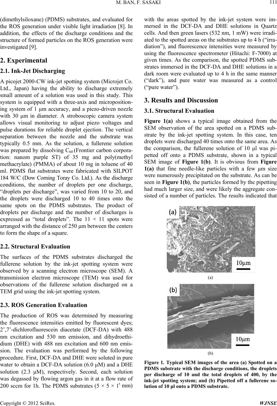 M. BAN, F. SASAKI 111 (dimethylsiloxane) (PDMS) substrates, and evaluated for the ROS generation under visible light irradiation [8]. In addition, the effects of the discharge conditions and the structure of formed particles on the ROS generation were investigated [9]. 2. Experimental 2.1. Ink-Jet Discharging A picojet 2000-CW ink-jet spotting system (Microjet Co. Ltd., Japan) having the ability to discharge extremely small amount of a solution was used in this study. This system is equipped with a three-axis and microposition- ing system of 1 μm accuracy, and a piezo-driven nozzle with 30 μm in diameter. A stroboscopic camera system allows visual monitoring to adjust piezo voltages and pulse durations for reliable droplet ejection. The vertical separation between the nozzle and the substrate was typically 0.5 mm. As the solution, a fullerene solution was prepared by dissolving C60 (Frontier carbon corpora- tion: nanom purple ST) of 35 mg and poly(methyl methacrylate) (PMMA) of about 10 mg in toluene of 40 ml. PDMS flat substrates were fabricated with SILPOT 184 W/C (Dow Corning Toray Co. Ltd.). As the discharge conditions, the number of droplets per one discharge, “droplets per discharge”, was varied from 10 to 20, and the droplets were discharged 10 to 40 times onto the same spots on the PDMS substrates. The product of droplets per discharge and the number of discharges is expressed as “total droplets”. The 11 × 11 spots were arranged with the distance of 250 μm between the centers to form the shape of a square. 2.2. Structural Evaluation The surfaces of the PDMS substrates discharged the fullerene solution by the ink-jet spotting system were observed by a scanning electron microscope (SEM). A transmission electron microscope (TEM) was used for observations of the fullerene solution discharged on a TEM grid using the ink-jet spotting system. 2.3. ROS Generation Evaluation The production of ROS was determined by measuring the fluorescence intensities emitted by fluorescent dyes; 2’,7’-dichlorofluorescein diacetate (DCF-DA) with 488 nm excitation and 530 nm emission, and dihydroethi- dium (DHE) with 488 nm excitation and 600 nm emis- sion. The evaluation was performed by the following procedure. First, DCF-DA and DHE were soluted in pure water to obtain a DCF-DA solution (6.0 μM) and a DHE solution (2.3 μM), respectively. Second, each solution was degassed by flowing argon gas in it at a flow rate of 200 sccm for 1h. The PDMS substrates (5 × 5 × 1t mm) with the areas spotted by the ink-jet system were im- mersed in the DCF-DA and DHE solutions in Quartz cells. And then green lasers (532 nm, 1 mW) were irradi- ated to the spotted areas on the substrates up to 4 h (“irra- diation”), and fluorescence intensities were measured by using the fluorescence spectrometer (Hitachi: F-7000) at given times. As the comparison, the spotted PDMS sub- strates immersed in the DCF-DA and DHE solutions in a dark room were evaluated up to 4 h in the same manner (“dark”), and pure water was measured as a control (“pure water”). 3. Results and Discussion 3.1. Structural Evaluation Figure 1(a) shows a typical image obtained from the SEM observation of the area spotted on a PDMS sub- strate by the ink-jet spotting system. In this case, ten droplets were discharged 40 times onto the same area. As the comparison, the fullerene solution of 10 μl was pi- petted off onto a PDMS substrate, shown in a typical SEM image of Figure 1(b). It is obvious from Figure 1(a) that fine needle-like particles with a few μm size were numerously precipitated on the substrate. As can be seen in Figure 1(b), the particles formed by the pipetting had much larger size, and were likely the aggregate con- sisted of a number of particles. The results indicated that (a) (b) Figure 1. Typical SEM images of the area (a) Spotted on a PDMS substrate with the discharge conditions, the droplets per discharge of 10 and the total droplets of 400, by the ink-jet spotting system; and (b) Pipetted off a fullerene so- lution of 10 μl onto a PDMS substrate. Copyright © 2012 SciRes. WJNSE 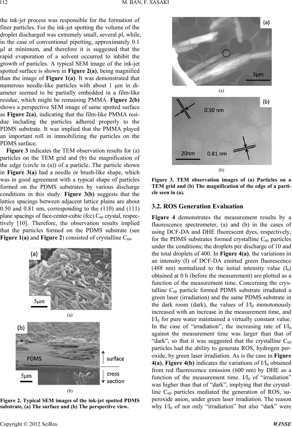 M. BAN, F. SASAKI 112 the ink-jet process was responsible for the formation of finer particles. For the ink-jet spotting the volume of the droplet discharged was extremely small, several pl, while, in the case of conventional pipetting, approximately 0.1 μl at minimum, and therefore it is suggested that the rapid evaporation of a solvent occurred to inhibit the growth of particles. A typical SEM image of the ink-jet spotted surface is shown in Figure 2(a), being magnified than the image of Figure 1(a). It was demonstrated that numerous needle-like particles with about 1 μm in di- ameter seemed to be partially embedded in a film-like residue, which might be remaining PMMA. Figure 2(b) shows a perspective SEM image of same spotted surface as Figure 2(a), indicating that the film-like PMMA resi- due including the particles adhered properly to the PDMS substrate. It was implied that the PMMA played an important roll in immobilizing the particles on the PDMS surface. Figure 3 indicates the TEM observation results for (a) particles on the TEM grid and (b) the magnification of the edge (circle in (a)) of a particle. The particle shown in Figure 3(a) had a needle or brush-like shape, which was in good agreement with a typical shape of particles formed on the PDMS substrates by various discharge conditions in this study. Figure 3(b) suggests that the lattice spacings between adjacent lattice plains are about 0.50 and 0.81 nm, corresponding to the (110) and (111) plane spacings of face-center-cubic (fcc) C60 crystal, respec- tively [10]. Therefore, the observation results implied that the particles formed on the PDMS substrate (see Figure 1(a) and Figure 2) consisted of crystalline C60. (a) (b) Figure 2. Typical SEM images of the ink-jet spotted PDMS substrate, (a) The surface and (b) The perspective view. (a) (b) Figure 3. TEM observation images of (a) Particles on a TEM grid and (b) The magnification of the edge of a parti- cle seen in (a). 3.2. ROS Generation Evaluation Figure 4 demonstrates the measurement results by a fluorescence spectrometer, (a) and (b) in the cases of using DCF-DA and DHE fluorescent dyes, respectively, for the PDMS substrates formed crystalline C60 particles under the conditions; the droplets per discharge of 10 and the total droplets of 400. In Figure 4(a), the variations in an intensity (I) of DCF-DA emitted green fluorescence (488 nm) normalized to the initial intensity value (I0) obtained at 0 h (before the measurement) are plotted as a function of the measurement time. Concerning the crys- talline C60 particle formed PDMS substrate irradiated a green laser (irradiation) and the same PDMS substrate in the dark room (dark), the values of I/I0 monotonously increased with an increase in the measurement time, and I/I0 for pure water maintained a virtually constant value. In the case of “irradiation”, the increasing rate of I/I0 against the measurement time was larger than that of “dark”, so that it was suggested that the crystalline C60 particles had the ability to generate ROS, hydrogen per- oxide, by green laser irradiation. As is the case in Figure 4(a), Figure 4(b) indicates the variations of I/I0 obtained from red fluorescence emission (600 nm) by DHE as a function of the measurement time. I/I0 of “irradiation” was higher than that of “dark”, implying that the crystal- line C60 particles mediated the generation of ROS, su- peroxide anion, under green laser irradiation. The reason why I/I0 of not only “irradiation” but also “dark” were Copyright © 2012 SciRes. WJNSE 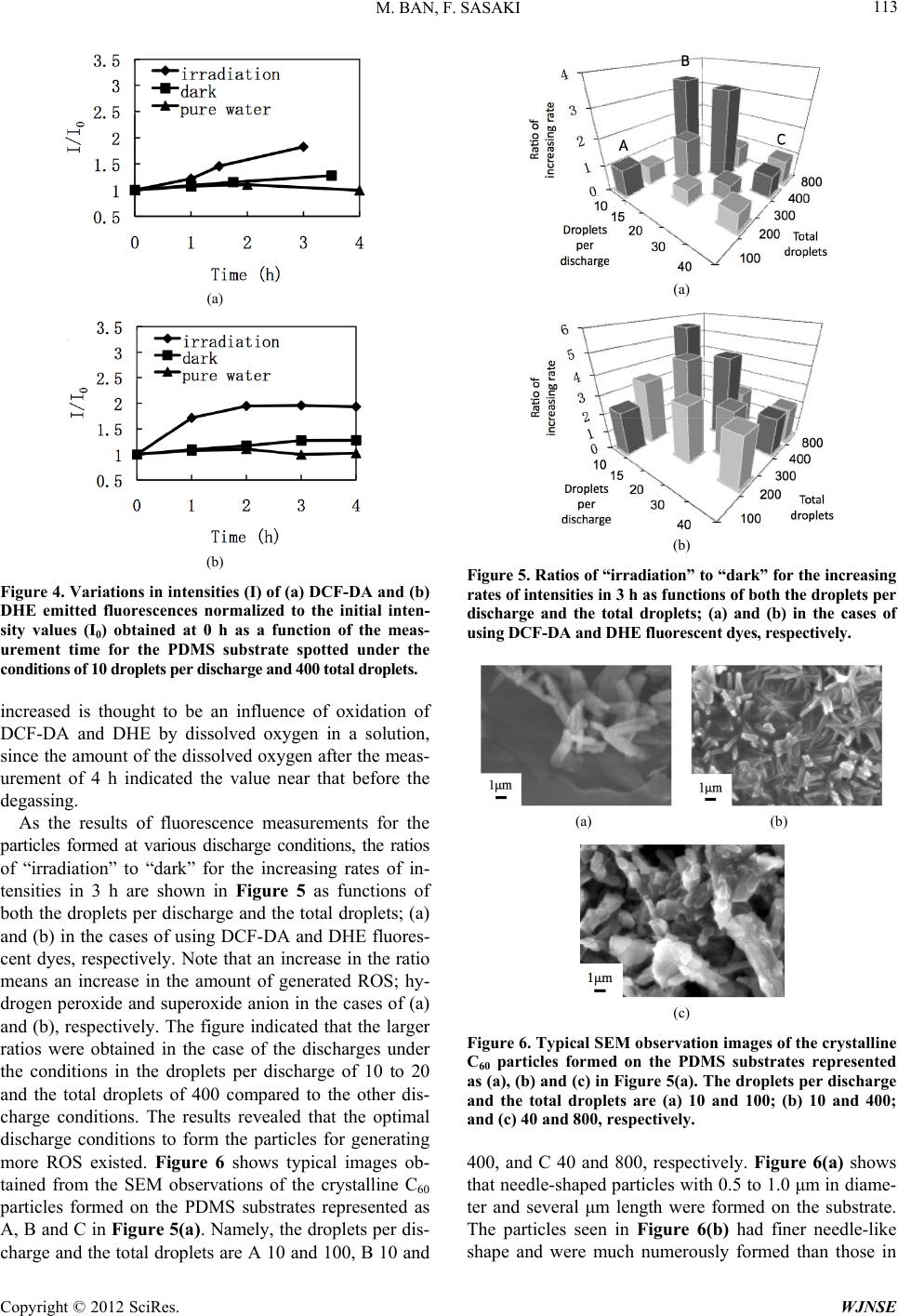 M. BAN, F. SASAKI 113 (a) (b) Figure 4. Variations in intensities (I) of (a) DCF-DA and (b) creased is thought to be an influence of oxidation of sults of fluorescence measurements for the pa DHE emitted fluorescences normalized to the initial inten- sity values (I0) obtained at 0 h as a function of the meas- urement time for the PDMS substrate spotted under the conditions of 10 droplets per discharge and 400 total droplets. in DCF-DA and DHE by dissolved oxygen in a solution, since the amount of the dissolved oxygen after the meas- urement of 4 h indicated the value near that before the degassing. As the re rticles formed at various discharge conditions, the ratios of “irradiation” to “dark” for the increasing rates of in- tensities in 3 h are shown in Figure 5 as functions of both the droplets per discharge and the total droplets; (a) and (b) in the cases of using DCF-DA and DHE fluores- cent dyes, respectively. Note that an increase in the ratio means an increase in the amount of generated ROS; hy- drogen peroxide and superoxide anion in the cases of (a) and (b), respectively. The figure indicated that the larger ratios were obtained in the case of the discharges under the conditions in the droplets per discharge of 10 to 20 and the total droplets of 400 compared to the other dis- charge conditions. The results revealed that the optimal discharge conditions to form the particles for generating more ROS existed. Figure 6 shows typical images ob- tained from the SEM observations of the crystalline C60 particles formed on the PDMS substrates represented as A, B and C in Figure 5(a). Namely, the droplets per dis- charge and the total droplets are A 10 and 100, B 10 and (a) (b) Figure 5. Ratios of “irradiation” to “dark” for the increasing rates of intensities in 3 h as functions of both the droplets per discharge and the total droplets; (a) and (b) in the cases of using DCF-DA and DHE fluorescent dyes, respectively. (a) (b) (c) Figure 6. Typical SEM obseion images of the crystalline 00, and C 40 and 800, respectively. Figure 6(a) shows rvat C60 particles formed on the PDMS substrates represented as (a), (b) and (c) in Figure 5(a). The droplets per discharge and the total droplets are (a) 10 and 100; (b) 10 and 400; and (c) 40 and 800, respectively. 4 that needle-shaped particles with 0.5 to 1.0 μm in diame- ter and several μm length were formed on the substrate. The particles seen in Figure 6(b) had finer needle-like shape and were much numerously formed than those in Copyright © 2012 SciRes. WJNSE  M. BAN, F. SASAKI 114 Figure 6(a). For Figure 6(c), the particles having a shape of relatively grain were synthesized, and formed sticking to each other. Therefore, it is noted that at the optimal dis- charge conditions for generating more ROS, that is to say, the droplets per discharge of 10 to 20 and the total drop- lets of 400, the finer needle-like particles were three-di- mensionally formed as seen in Figure 6(b). Additionally, the SEM observation results of all ink-jet spotted PDMS substrates suggested that the particles formation state was transformed from planar into three-dimensional structure, and from needle-shaped into grain-shaped particles with an increase in both the droplets per discharge and the total droplets. To investigate the relation between the formation state of les formed in the various di particles and the ROS production, the total surface area of the crystalline C60 particles formed on the PDMS substrate was estimated by the following calculation pro- cedure. The total amount of the fullerene solution dis- charged was calculated by the product of an amount of one droplet (4.2 pl, supposing that the diameter was 20 μm) and the number of total droplets. The weight of all crystalline C60 particles formed on the PDMS substrate was calculated with the total discharged amount and the concentration of the C60 dissolved in the solution, 35 mg/ml. Here, the weight of one crystalline C60 particle was obtained using the density of C60, 1.73 g/cm3 [11], and the sizes of the crystalline C60 particles measured from the SEM images. Assuming that all dissolved fulle- rene in the fullerene solution was precipitated as the crys- talline C60 particles, the number of the crystalline C60 particles formed on the PDMS substrate was obtained from the weight of one crystalline C60 particle and the calculated weight of all crystalline C60 particles formed on the PDMS substrate. Multiplying the surface area of one crystalline C60 particle, which was calculated from the size measured using the SEM observation results, by the number of the crystalline C60 particles, the total sur- face area of the crystalline C60 particles formed on the PDMS substrate was obtained. For the crystalline C60 partic scharge conditions, the variation of the ratio of in- creasing rate in the case of using DCF-DA (see Figure 5 (a)) as a function of the calculated total surface area of the particles is shown in Figure 7. The figure revealed that there appeared to be two tendencies (plots of group I and II) of the ratio of increasing rate against the total surface area of the particles. That is to say, for group I and II, the ratios of increasing rate were increased and almost unchanged with an increase in the surface area of the particles, respectively. The crystalline C60 particles belonging to group I had a three-dimensionally formed finer structure as observed in the image of Figure 6(b), and it was suggested that larger exposed particle sur- face led to more production of ROS. Meanwhile, for the Figure 7. Variation in the ratio of increasing rate as a fnc- rystalline C60 particles in group II the increment of the 4. Conclusion particles were formed on the PDMS 5. Acknowledgements xpress many thanks to Mr. REFERENCES [1] E. Nakamura lized Fullerenes in u tion of the total surface area calculated for the crystalline C60 particles formed under the various discharge conditions. The dotted lines are drawn to guide the eye. c surface area made little contribution to ROS generation because it was highly probable that the particles were stuck together to form larger clumps, as seen in Figure 6(c). The crystalline C60 substrates under the various discharge conditions by the ink-jet spotting system, and investigated for the relation- ships among the conditions, the shape and the structure of particles, and the ROS generation. The fluorescence measurement results implied that the formed crystalline C60 particles mediated the generation of ROS, hydrogen peroxide and superoxide anion. The optimal ink-jet dis- charge conditions, the droplets per discharge of 10 to 20 and the total droplets of 400, existed for synthesizing the crystalline C60 particles to generate more ROS. It was indicated from the SEM observation results that under the optimal conditions the finer needle-like particles were three-dimensionally formed. It was found that there was a possibility that increasing the surface area of crystalline C60 particles led to an increase in the ROS generation amount, considering that the particles formed under the optimal conditions had larger surface area. The authors would like to e Manabu Suzuki of Research & Development Center for Advanced Materials and Technology, Nippon Institute of Technology for TEM observations and the specimen prepa- ration. This work was supported by KAKENHI (22510125). and H. Isobe, “Functiona Water,” Accounts of Chemical Research, Vol. 36, No. 11, Copyright © 2012 SciRes. WJNSE 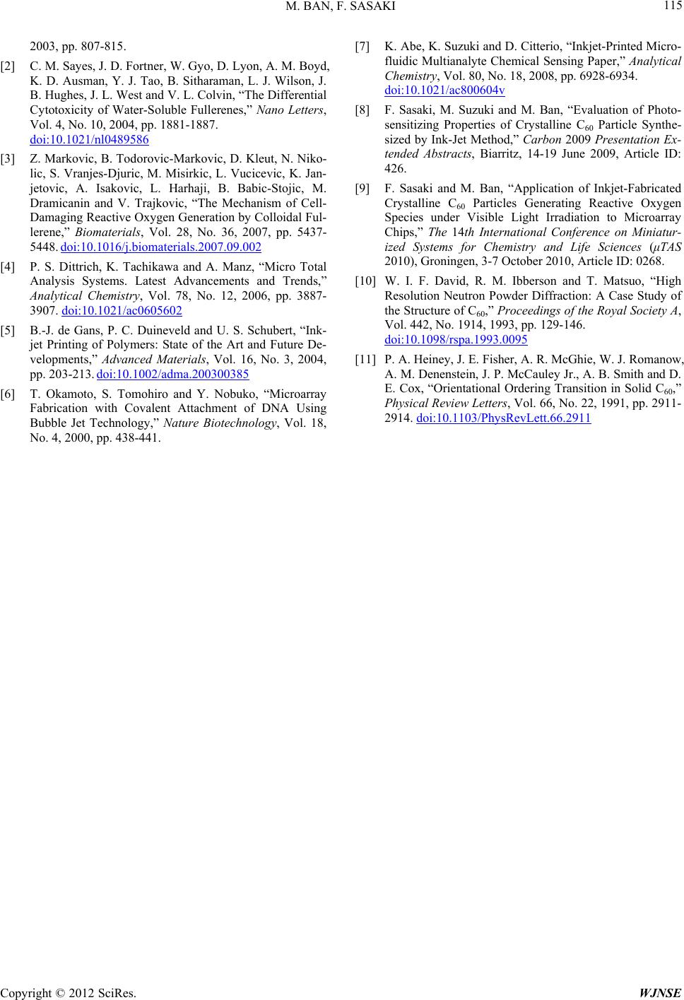 M. BAN, F. SASAKI Copyright © 2012 SciRes. WJNSE 115 ortner, W. Gyo, D. Lyon, A. M. 2003, pp. 807-815. [2] C. M. Sayes, J. D. F Boyd, K. D. Ausman, Y. J. Tao, B. Sitharaman, L. J. Wilson, J. B. Hughes, J. L. West and V. L. Colvin, “The Differential Cytotoxicity of Water-Soluble Fullerenes,” Nano Letters, Vol. 4, No. 10, 2004, pp. 1881-1887. doi:10.1021/nl0489586 [3] Z. Markovic, B. Todorovic-Markovic, D. Kleut, N. Niko- lic, S. Vranjes-Djuric, M. Misirkic, L. Vucicevic, K. Jan- jetovic, A. Isakovic, L. Harhaji, B. Babic-Stojic, M. Dramicanin and V. Trajkovic, “The Mechanism of Cell- Damaging Reactive Oxygen Generation by Colloidal Ful- lerene,” Biomaterials, Vol. 28, No. 36, 2007, pp. 5437- 5448. doi:10.1016/j.biomaterials.2007.09.002 [4] P. S. Dittrich, K. Tachikawa and A. Manz, “Micro Total Analysis Systems. Latest Advancements and Trends,” Analytical Chemistry, Vol. 78, No. 12, 2006, pp. 3887- 3907. doi:10.1021/ac0605602 [5] B.-J. de Gans, P. C. Duineveld and U. S. Schubert, “Ink- jet Printing of Polymers: State of the Art and Future De- velopments,” Advanced Materials, Vol. 16, No. 3, 2004, pp. 203-213. doi:10.1002/adma.200300385 [6] T. Okamoto, S. Tomohiro and Y. Nobuko, “Microarray erio, “Inkjet-Printed Micro- Fabrication with Covalent Attachment of DNA Using Bubble Jet Technology,” Nature Biotechnology, Vol. 18, No. 4, 2000, pp. 438-441. [7] K. Abe, K. Suzuki and D. Citt fluidic Multianalyte Chemical Sensing Paper,” Analytical Chemistry, Vol. 80, No. 18, 2008, pp. 6928-6934. doi:10.1021/ac800604v [8] F. Sasaki, M. Suzuki and M. Ban, “Evaluation of Photo- saki and M. Ban, “Application of Inkjet-Fabricated h sensitizing Properties of Crystalline C60 Particle Synthe- sized by Ink-Jet Method,” Carbon 2009 Presentation Ex- tended Abstracts, Biarritz, 14-19 June 2009, Article ID: 426. [9] F. Sa Crystalline C60 Particles Generating Reactive Oxygen Species under Visible Light Irradiation to Microarray Chips,” The 14th International Conference on Miniatur- ized Systems for Chemistry and Life Sciences (μTAS 2010), Groningen, 3-7 October 2010, Article ID: 0268. [10] W. I. F. David, R. M. Ibberson and T. Matsuo, “Hig Resolution Neutron Powder Diffraction: A Case Study of the Structure of C60,” Proceedings of the Royal Society A, Vol. 442, No. 1914, 1993, pp. 129-146. doi:10.1098/rspa.1993.0095 [11] P. A. Heiney, J. E. Fisher, A. R. McGhie, W. J. Romanow, A. M. Denenstein, J. P. McCauley Jr., A. B. Smith and D. E. Cox, “Orientational Ordering Transition in Solid C60,” Physical Review Letters, Vol. 66, No. 22, 1991, pp. 2911- 2914. doi:10.1103/PhysRevLett.66.2911 |