

Paper Menu >>
Journal Menu >>
 Int. J. Communications, Network and System Sciences, 2010, 3, 540-547 doi:10.4236/ijcns.2010.36072 Published Online June 2010 (http://www.SciRP.org/journal/ijcns/). Copyright © 2010 SciRes. IJCNS Uplink Performance Evaluation of CDMA Communication System with RAKE Receiver and Multiple Access Interference Cancellation Ayodeji J. Bamisaye, Michael O. Kolawole Department of Electrical and Electronics Engineering the Federal University of Technology, Akure, Nigeria E-mail: [email protected] and [email protected] Received January 26, 2010; revised March 2, 2010; accepted April 10, 2010 Abstract In CDMA communication systems, all the subscribers share the common channel. The limitation factor on the system’s capacity is not the bandwidth, but multiuser interference and the near far problem. This paper models CDMA system from the perspective of mobile radio channels corrupted by additive white noise gen- erated by multipath and multiple access interferences. The system’s receiver is assisted using different com- bining diversity techniques. Performance analysis of the system with these detect ion techniques is presented. The paper demonstrates that combining diversity techniques in the system’s receivers markedly improve the performance of CDMA systems. Keywords: CDMA, Multipath Diversity, Multiple Access Interference Cancellation, Rake Receiver, Parallel Interference Cancellation 1. Introduction The mobile radio channel plays fundamental limitations on the performance of wireless communication systems. The transmission path between the transmitter and the receiver can vary from simple line-of-sight to one that is severely obstructed by buildings, mountains, and foliage. Unlike wired channels th at are stationary and predictable, radio channels are extremely random and do not offer easy analysis. Even the speed of motion impacts how rapidly the signal level fades as mobile terminal moves in space. Modelling the radio channel has historically been one of the most difficult parts of mobile radio sys- tem design, and is typically done in a statistical fashion, based on measurements made specifically for intended communication system or spectrum allocation. Code Division Multiple Access (CDMA) is a multiple access technology that utilizes direct-sequence spread spectrum (DS-SS) techniques. With this technology comes a para- digm shift, including the use orthogonal or nearly or- thogonal codes (so-called spreading sequences) to modulate the transmitted bits. Contrary to the conven- tional frequency division multiple access (FDMA) and time division multiple access (TDMA) systems where noise rejection d eals, primarily with out-of-band noise, a CDMA system concerns mostly with inband noise. This noise may come from self-jamming (or self-noise), back- ground noise, man-made noise, inter-modulation, or noise generated in the receiver [1,2]. If one can reduce the unwanted in-band noise, such reduction translates directly into improved performance. Undesired noise comes from many different sources. This noise may come from natural or human sources. Naturally occur- ring noise includes atmospheric disturbances, back- ground noise, and thermal noise generated in the receiver itself. Through careful engineering, the effects of many unwanted signals can be reduced [3]. DS-CDMA is a multiple access system, where multiple users share a limited resource, the frequency. Conventional asynchro- nous DS-CDMA systems allow each user to transmit and receive independently. Each receiver performs a simple correlation between the received baseband signal and the corresponding user’s spreading sequence. In a low-noise channel with orthogonal spreading sequence,this app- roach would be optimal. Due to the synchronicity of us- ers and the need to support numerous users, such ortho- gonality is impossible, even on a hypothetical AWGN (additive white Gaussian noise) channel [4]. Thus, sys- tem performance rendered multiple-access interference (MAI) limited, and channel utilization is correspo ndingly low. This paper m odel s C DM A sy st em fr om t he pers pect ive  A . J. BAMISAYE ET AL.541 of mobile radio channels corrupted by additive white noise generated by multipath and multiple access inter- ferences. The system’s receiver is assisted using different combining diversity techniques. Performance analysis of the model with different detection techniques will be presented. 1.1. Mobile Radio Channel Model Mobile radio channel is one of the most important ele- ments in the mobile communication systems. When the signals are transmitted through Mobile radio channel, it is affected by shadow or large scale fading. Mobile communication is affected by multipath fading in addi- tion to shadow fading. Multipath fading is caused by atmospheric, scattering, and reflection from building and other object. Multipath channel can be classified as dis- crete (consisting of resolvable multipath components) and diffuse (consisting of irresolvable multipath compo- nents) [5,6]. Consequently, the multipath fading could affect the transmitted sig nals in two ways: due to disper- sion (also called time spreading or frequency selectivity), and due to time variant behaviour of the channel (due to motion of the receiver or changing environment such as of foliage or movement of reflectors and scatter). This means that the impulse response ,ht of mobile radio channel is time variant [6,7], and if , ht has a zero mean, then the en velope ht, has a Rayleigh distribu- tion with its probability density function described by 2 2 exp 2 rr pr 2 (1) where r is time dependent received signal (i.e., () () || j t rtr e , is its arbitrary phase) whose line of sight (LOS), specular, and diffuse components are as- sumed bounded in narrowband form, and 2 is the total power in the multipath signal. In this case the total power is considered to have zero-mean, amplitude fading. Otherwise, if the impulse response has a non-zero mean, then the envelope mobile radio channel would have a Rician distribution with its probability density function expressed as: 22 2 22 exp 2o rs r prI 2 r (2) where 2 s is the power of the line-of-sight component, and o I denotes the zeroth order Bessel function of the first kind argument (.). The Rayleigh distribution is a special case of Rician distribution when s = 0; i.e., wher e the LOS component is negligible. In most general case, the channel can be modelled as channel at time (t) to an impulse at time (t-τ). If x(t) represents the transmitted (or emitted) signal through noiseless mobile radio channels, the received signal, r(t) can be expressed as ,rthtxtd (3) If the channel information is considered ch , its distributed annel impulse response may be expressed as 1N 0 , j j j ht t (4) In view of (4) in (3), we write modified channel re- ceived signal: 1 0 N j j j rtxt j (5) β(t) is complex amplitude, j is the path delay, and N is 1.2. Rake Receiver onventional matched filters are single pa th detectors. In j the number of multipath components. In the wideband channel where the delay-line model had a large number of taps, not all the multipath components are likely to fade simultaneously. This may be used as a multipath diversity to improve the received signal SINR (carrier to interference plus noise ratio). Rake receiver, for instance, can be used to mitigate the effect of fading if the trans- mitted signal bandwidth is larger than the coherence bandwidth; a practical example is in the wideband- CDMA (WCDMA). C practice, when the transmitte d signal passes through mo- bile radio channel, duplicates of the transmitted signal are generated by reflection, refraction, and diffraction, and the signal power is distributed in multipath. In CDMA system, the transmitted signal bandwidth is much larger than the coherent bandwidth of the channel, in which case the channel is frequency selective [4,8,9]. For the frequency-selective channels, the received signals are multiple copies of the transmitted signals with different channel delays and fading, combining the multipath components as multipath diversity. Thus, if one of the multipath components is attenuated by fading, some oth- ers may not be and the receiver could use unfaded com- ponents to make the decision. The idea behind the rake reception technique is that the signals propagating through different multipath are received in individual fingers of the rake receiver and the outputs from these fingers are then coheren tly co mbined to prov id e the inpu t signal for the symbol decision. The received signal is chip matched and sampled at the chip rate. Figure 1, illustrates the structure of a typical rake receiver in which *() k s i and *,() km ci (k = 1, 2, ..., K; m = 1, 2, ..., M) rep- t, resply, the complex conjugate of chip- resenective channel matched sampled signature sequence of the user linear time-variant system [2] giving the response of the Copyright © 2009 SciRes. IJCNS 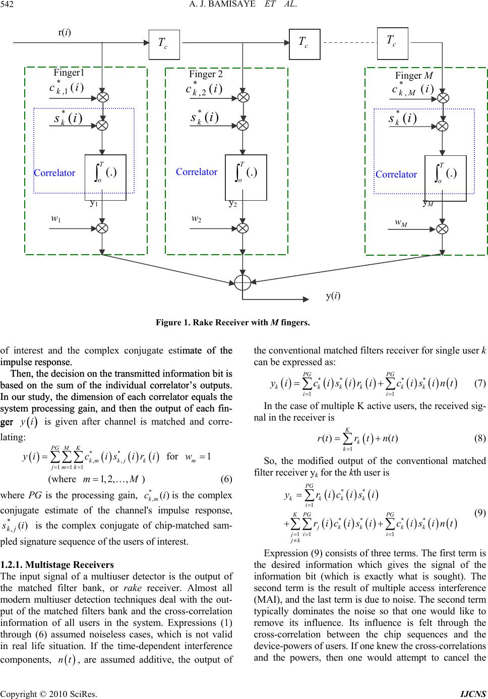 A. J. BAMISAYE ET AL. 542 f interest and the complex conjugate estimate of the n on the transmitted information bit is ba mate of the n on the transmitted information bit is ba o impulse response. Then, the decisio impulse response. Then, the decisio sed on the sum of the individual correlator’s outputs. In our study, the dimension of each correlator equals the system processing gain, and then the output of each fin- ger sed on the sum of the individual correlator’s outputs. In our study, the dimension of each correlator equals the system processing gain, and then the output of each fin- ger y i is given after channel is matched and corre- latin y g: for ** ,, 111 PG MK kmk jk jmk icisir i 1 m w (where ) (6) where PG gain, pled sig .2.1. Multistage Receivers r detector is the output of the conventional matched filters receiver for single user k In the case of multiple K active users, the received sig- nal in the receiver is So, the modified output of the co filter receiver yk for the kth user is (9) Expression (9) consists of three terms. The first term is the desired information which gives the signal of the in 1, 2,,mM is the processing *,() km ciis the complex conjugate estimate of the channepulse response, )( *,is jk is the complex conjugate of chip-matched sam- nature sequence of the users of interest. l's im 1 The input signal of a multiuse the matched filter bank, or rake receiver. Almost all modern multiuser detection techniques deal with the out- put of the matched filters bank and the cross-correlation information of all users in the system. Expressions (1) through (6) assumed noiseless cases, which is not valid in real life situation. If the time-dependent interference components, nt , are assumed additive, the output of can be expressed as: ** ** 1 PG PG kkkkkk i yicisiricisint (7) 1i () () K k rtr tnt (8) 1k nventional matched ** 1 PG kkkk i yricisi ** ** 11 1 KPG PG jkk kk ji i jk ri cisi cisint formation bit (which is exactly what is sought). The second term is the result of multiple access interference (MAI), and the last term is due to noise. The second term typically dominates the noise so that one would like to remove its influence. Its influence is felt through the cross-correlation between the chip sequences and the device-powers of users. If o ne knew the cross-correlations and the powers, then one would attempt to cancel the r(i) )( *is k )( *is k )( *is k c)( *1, i k )( *2, ick)( *,ic Mk c T c T c T Correlator T o(.) w1 Finger1 Correlator T o(.) w2 Finger 2 Correlator T o(.) M w Finger M y(i) Figure 1. Rake Receiver with M fingers. y1 y2 yM Copyright © 2010 SciRes. IJCNS  A . J. BAMISAYE ET AL.543 in front end, a SIC receiver (ordecorrelator) can be used [1 on and Results erformed for different nce cancellation); ting Detector and M is clearly stated. It is assumed that the system us ta is obtained by passing the soft de Simulations were performed for 10 active users sending to 100total of 10000 symbols. The in cance- lli Similar parameters used in 1.3.1 are used in this analysis In add are updated ran- . Th ectively, while other pa performance is the sa effect of one user upon another. This is, in fact, the intuitive motivation for interference cancellation scheme. The difference between multistage receivers and suc- cesssive interference canceller (SIC) receivers is that stead of using previous bit decisions to cancel interfer- eence from desired user’s signal as in SIC, tentative de- cisions on each user are used to improve signal quality [10]. Receiver structure is called multistage, since when decisions are made, they can be used to either make a final decision on data or to enhance the signal through cancellation. Reference signals are based on initial bit estimates, which are then subtracted from received signal to produce a cleaned spread signal for next stage. Since all signals are detected at each stage simultaneously, multistage receivers are also called parallel interference cancellers (PIC). A two-user multistage receiver is shown in Figure 2. The p-stage receiver outputs are 1,pp k yt , where 1, 2,p. Instead of a conventional (matched filter) receiver a 1]. Performance of PIC is best when received signal powers are equal. Capacity of the system is limited by hardware. 1.3. Simulati Performance evaluations were p scenarios using: 1) Conventional matched filters receiver with PIC (parallel interfere 2) Rake receiver with PIC; 3) Rake receiver with Decorrela MSE; and 4) Conventional matched filters receiver and rake re- ceiver. For each analysis, the number of users’ symbols tran- smitted es unencoded BPSK signal, as well as no pulse- shaping filter. Each transmitted MS within each loop sends a block of data bits of known length. The input of MUD (multi user detection) is the soft decision of either rake receiver or conventional matched filters. In the simulation, the sub-optimum linear MUD decorrelating detector, linear minimum mean squared error (LMMSE) detector, and nonlinear sub-optimum PIC were built for the multishot model. In relation to the decision operation, the hard decision output of received da cision output through the design circuit, which repre- sents any sign function for BPSK. Also, we make the number of channel paths P equal the number of fingers M to make the rake receiver simpler in structure. In a less equivalent case, that is, when M < P or M > P, the system performance degrades. Therefore, the matched case pro- vides the optimally achievable performance reference. 1.3.1. Performance of Conventional Matched Filters Receiver with PIC 10 symbols within each loop. The maximum loop equals . The users send a data are then spread by Walsh code and scrambled by Gold code with processing gain of 32. The channel pa- rameters are updated randomly in each loop. Simulation results are shown in Figure 3, which de- monstrates progressive improvement in the system per- formance with diversity combining techniques ng multiple access interferences. 1.3.2. Performance of Conventional Matched Filters Receiver and Rake Receiver except the processing gain, PG, which is increased to 64. ition, the channel parameters domly in each loop and the number of paths for each user changes randomly over (2-6). Two tests were carried out in this subsection: (i) to investigate the effect of rake receiver in the system for a single user and (ii) to inves- tigate the effect of rake receiver and conventional (matched filter) receiver with a range of channel paths. Figure 4 shows the performance with rake receiver and without rake receiver for a single user. In the re- ceiver, ‘equal gain combining’ method is used in rake e analysis demonstrates that lowering the SNR does not improve the system when SNR equals 20 dB, the BER is 10–2.9 and 10–1.9 respectively for conventional matched filter receiver and rake receiver. In contrast, improvement in system performance can be achieved by increasing SNR in both sche m e s. In the case of test (ii), an AGWN is assumed in the channel paths. The number of users and the processing gain are decreased to 6 and 8 resp rameters are the same as previous simulations. The channel parameters are updated randomly in each loop, and the simulation computes for the different values of channel path, as shown in Figure 5. Figure 5 shows the performance of the rake and con- ventional receivers for a number of multipath scenarios. In the case of one path, the system me for matched filter (MF) and rake receiver. But in the case of multipaths; for example, (4-path) the system performance with conventional matched filter degrades, whereas the system performance with rake receiver im- proves. Also, for the case of (7-path) the performance of MF becomes very poor, but improves markedly with rake receiver. As a result, the system performance can be deduced as increasing when diversity scheme is em- ployed. Under Gaussian noise as interferer, the system performance improves with in creasing channel path with the rake receiver, which might not be optimal in real life situation. Copyright © 2009 SciRes. IJCNS 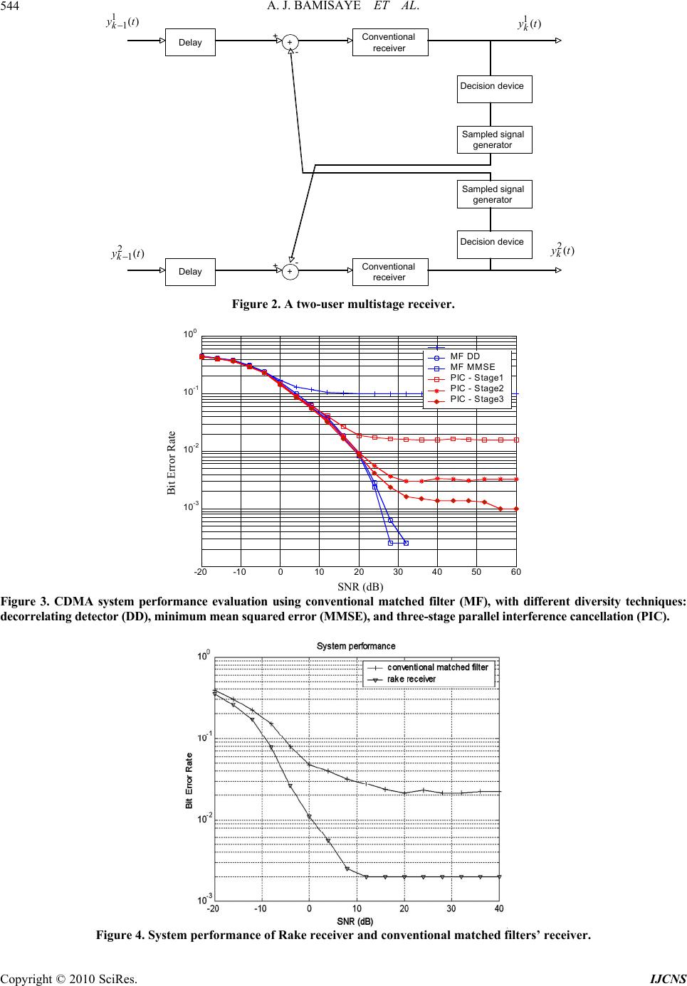 A. J. BAMISAYE ET AL. 544 Delay +Conventional receiver Decision device Sampled signal generator Sampled signal generator Decision device Delay +Conventional receiver + - yk1 1t + - yk1 2t yk 1t 1()yt 1() k yt 1k yk 2t 2() k yt 21() k yt Figure 2. A two-user multistage receiver. -20 -10 010 20 30 40 50 60 10-3 10-2 10-1 100 MF DD MF MMSE P IC - S tage1 P IC - S tage2 P IC - S tage3 Bit Error Rate Figure 3. CDMA system performance evaluation using conventional matched filter (MF), with different diversity techniques: decorrelating detector (DD), m mean squared error (MMSE) , and th ree-stage parallel internce cancellation (PIC). minimu fere SNR (dB) Figure 4. System performance of Rake receiver and conventional matched filters’ receiver. Copyright © 2010 SciRes. IJCNS 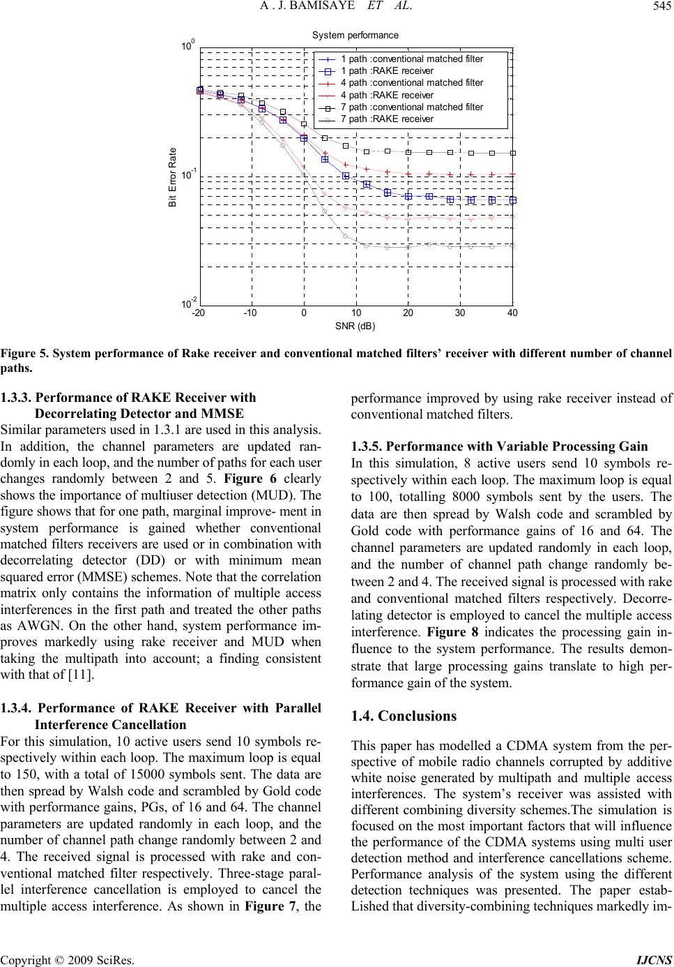 A . J. BAMISAYE ET AL. Copyright © 2009 SciRes. IJCNS 545 -20 -10 010 20 30 40 10 0 10 -2 10 -1 S y st em performance Bit Error Rate 1 pat h : conve nt i onal m at ched fil t er 1 path :RA K E rec ei ver 4 path :c onvent i onal matc hed fil ter 4 path :RA K E rec ei ver 7 pat h : conve nt i onal m at ched fil t er 7 path :RA K E rec ei ver SNR (dB ) Figure 5. System performance of Rake receiver and conventional matched filters’ receiver with different number of channel paths. 1.3.3. Performance of RAKE Receiver with Decorrelating Detec tor and MMSE Similar parameters used in 1.3.1 are used in this analysis. In addition, the channel parameters are updated ran- domly in each loop, and the number of paths for each user changes randomly between 2 and 5. Figure 6 clearly shows the importance of multiuser detection (MUD). Teh figure shows that for one path, marginal improve- ment in system performance is gained whether conventional matched filters receivers are used or in combination with decorrelating detector (DD) or with minimum mean squared error (MMSE) schemes. Note that the correlation matrix only contains the information of multiple access interferences in the first path and treated the other paths as AWGN. On the otherd, system performance im- at of [11]. 1.3.4.ith Parallel performance improved by using rake receiver instead of conventional matched filters. 1.3.5. Perf or mance with Var iable Processing Gain In this simulation, 8 active users send 10 symbols re- spectively within each loop. The maximum loop is equal to 100, totalling 8000 symbols sent by the users. The data are then spread by Walsh code and scrambled by Gold code with performance gains of 16 and 64. The channel parameters are updated randomly in each loop, and the number of channel path change randomly be- tween 2 and 4. The received signal is processed with rake and conventional matched filters respectively. Decorre- lating detector is employed to cancel the multiple access interference. Figure 8 indicates the processing gain in- strate that large processing gains translate to high per- CDMA system from the per- pective of mobile radio channels corrupted by additive interfver was assisted with han proves markedly using rake receiver and MUD when taking the multipath into account; a finding consistent ith th fluence to the system performance. The results demon- w Performance of RAKE Receiver w Interference Cancellation For this simulation, 10 active users send 10 symbols re- spectively within each loop. The maximum loop is equal to 150, with a total of 15000 symbols sent. The data are then spread by Walsh code and scrambled by Gold code with performance gains, PGs, of 16 and 64. The chann el parameters are updated randomly in each loop, and the number of channel path change randomly between 2 and 4. The received signal is processed with rake and con- ventional matched filter respectively. Three-stage paral- lel interference cancellation is employed to cancel the multiple access interference. As shown in Figure 7, the formance gain of the system. 1.4. Conclusions This paper has modelled a s white noise generated by multipath and multiple access erences. The system’s recei different combining diversity schemes.The simulation is focused on the most important factors that will influence the performance of the CDMA systems using multi user detection method and interference cancellations scheme. Performance analysis of the system using the different detection techniques was presented. The paper estab- Lished that diversity-combining techniques markedly im- 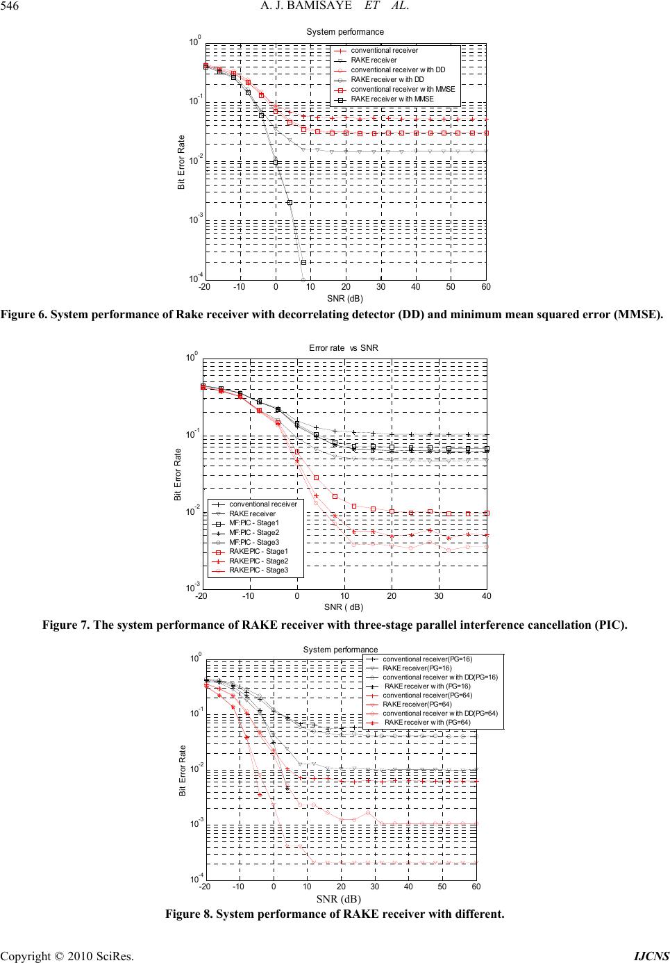 A. J. BAMISAYE ET AL. 546 -20 -1001020 304050 60 10 -4 10 -3 10 -2 10 -1 10 0 Sys t em pe NR e rformance conventional receiver RAKE receiver conventio nal receiver with DD RAKE receiver with DD conventio nal receiver with MMS E AKE receiver with MMSE R Ra t S B i t Error imum mean squared error (MMSE). (dB) Figure 6. System performan ce of Rak e receiver with decorrela ting detector (DD) and min -20 -10 010 20 3040 10 -3 10 -2 10 -1 10 0 E rr or ra te vs SNR B i t E rror Rate conventional receiver RAKE receiver MF:PIC - Stage1 MF:PIC - Stage2 MF:PIC - Stage3 RAKE:PIC - Stage1 RAKE:PIC - Stage2 RAKE:PIC - Stage3 SNR ( dB) Figure 7. The system performance of RAKE receiver with three-stage parallel interference cancellation (PIC). -20 -10 01020 30 40 50 60 10 -4 10 -3 10 -2 10 -1 10 0 S y st em pe rformance S NR (in dB) B i t Error Rate conventional receiver(PG=16) RAKE receiver(PG=16) conventional receiver with DD(PG=16) RAKE receiver with (PG= 16) conventional receiver(PG=64) RAKE receiver(PG=64) conventional receiver with DD(PG=64) RAKE receiver with (PG= 64) Figure 8. System performance of RAKE receiver with differen SNR (dB)t. Copyright © 2010 SciRes. IJCNS 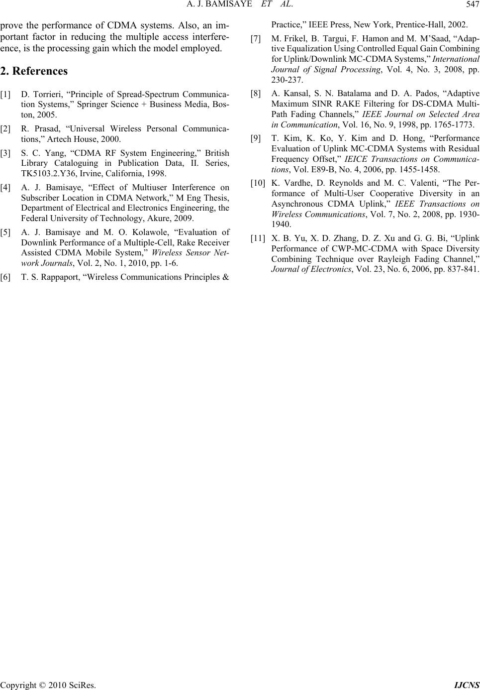 A. J. BAMISAYE ET AL.547 prove t portant factor in reducing the multiple access interfere- ence, is the processing gain which the model employed. 2. References [1] D. Torrieri, “Principle of Spread-Spectrum Communica- tion Systems,” Springer Science + Business Media, Bos- ton, 2005. [2] R. Prasad, “Universal Wireless Personal Communica- tions,” Artech House, 2000. [3] S. C. Yang, “CDMA RF System Engineering,” British Library Cataloguing in Publication Data, II. Series, TK5103.2.Y36, Irvine, California, 1998. [4] A. J. Bamisaye, “Effect of Multiuser Interference on Subscriber Location in CDMA Network,” M Eng Thesis, Department of Electrical and Electronics Engineering, the Federal University of Technology, Akure, 2009. ] A. J. Bamisaye and M. ] T. S. Rappaport, “Wireless Communications Principles & 02. [7] M. Frikel, B. Targui, F. Hamon and M. M’Saad, “Adap- tive Equalization Using Controlled Equal Gain Co mbining for Uplink/Downlink MC-CDMA Systems,” International Journal of Signal Processing, Vol. 4, No. 3, 2008, pp. 230-237. [8] A. Kansal, S. N. Batalama and D. A. Pados, “Adaptive Maximum SINR RAKE Filtering for DS-CDMA Multi- Path Fading Channels,” IEEE Journal on Selected Area in Communication, Vol. 16, No. 9, 1998, pp. 1765-1773. [9] T. Kim, K. Ko, Y. Kim and D. Hong, “Performance Evaluation of Uplink MC-CDMA Systems with Residual Frequency Offset,” IEICE Transactions on Communica- tions, Vol. E89-B, No. 4, 2006, pp. 1455-1458. [10] K. Vardhe, D. Reynolds and M. C. Valenti, “The Per- formance of Multi-User Cooperative Diversity in an Asynchronous CDMA Uplink,” IEEE Transactions on Wireless Communications, Vol. 7, No. 2, 2008, pp. 1930- k ty he performance of CDMA systems. Also, an im- Practice,” IEEE Press, New York, Prentice-Hall, 20 [5 O. Kolawole, “Evaluation of 1940. [11] Downlink Performance of a Multiple-Cell, Rake Receiver Assisted CDMA Mobile System,” Wireless Sensor Net- work Journals, Vol. 2, No. 1, 2010, pp. 1-6. [6 X. B. Yu, X. D. Zhang, D. Z. Xu and G. G. Bi, “Uplin Performance of CWP-MC-CDMA with Space Diversi Combining Technique over Rayleigh Fading Channel,” Journal of Electronics, Vol. 23, No. 6, 2006, pp. 837-841. Copyright © 2010 SciRes. IJCNS |