

Paper Menu >>
Journal Menu >>
 Materials Sciences and Applications, 2012, 3, 213-217 http://dx.doi.org/10.4236/msa.2012.34031 Published Online April 2012 (http://www.SciRP.org/journal/msa) 213 Synthesis of High-Density Vertically Aligned Carbon Nanotubes Using Ultrasonic Nebulizer Jianhui Zhang1,2, Wei Li1,3, Tetsuo Soga4, Takashi Jimbo4, Takayoshi Tanji1,2 1EcoTopia Science Institute, Nagoya University, Nagoya, Japan; 2Global Research Center for Environment and Energy Based on Nanomaterials Science, Nagoya, Japan; 3Graduate School of Engineering, Nagoya University, Nagoya, Japan; 4Department of Fron- tier Materials, Nagoya Institute of Technology, Nagoya, Japan. Email: [email protected] Received October 17th, 2011; revised December 27th, 2011; accepted February 22nd, 2012 ABSTRACT Vertically aligne d carbon nano tubes (VACNTs) arr ay with high density h ave been synthe sized from a mixture of f erro- cene and ethanol using ultrasonic nebulizer techniques. Using scanning electron microscopy (SEM) and transmission electron microscopy (TEM) as well as Raman spectroscopy, investigations reveal that the vertically aligned CNTs are multi-wall CNTs with well-ordered graphene sheets and are about 20 - 50 nm in diameter. We found that high density vertically aligned CNTs can be synthesized at 750˚C - 850˚C and that the length and density of vertically aligned CNTs increase with increasing growth temperatures. In addition, the single-walls CNTs have well-ordered graphene sheet and are about 2 nm in diameter on silicon substrates at 650˚C. Keywords: Carbon Nanotubes; Chemical Vapor Deposition; Transmission Electron Microscope 1. Introduction Since the discovery of carbon nanotubes (CNTs) [1] at- tempts have been extensively explored to take advantage of their unique properties for specific applications due to their unique morphological characteristics [2]. Potential technical applications in the area of electronic devices [3] and electron field emissions [4] have been proposed or explored. To understand their intrinsic properties, it is necessary to produce highly oriented CNTs [5]. Verti- cally aligned CNTs can be produced using various che mi- cal vapor deposition (CVD) methods, such as the hot filament CVD [6], plasma enhanced CVD [7] and ther- mal CVD [8]. Among these synthesis methods, the ther- mal CVD has been widely used, as it provides a way for large area synthesis of vertically aligned CNTs for elec- tron emitters. In many cases, the spray pyrolysis CVD method has been successfully applied in making CNTs for many years [9]. It is also an important method for the synthesis of vertically aligned CNTs and considerable progress has been achieved [10]. By this method of CVD, the high density oriented CNTs generally need pre-pat- terned metal catalysts substrate, and a carbon source gas is introduced into the quartz tube. The high density ori- ented CNTs are grown on this catalyst-coated substrate using a pyrolysis of the carbon source gas. In this study, we demonstrate the synthesis of high density oriented CNTs using the ultrasonic nebulizer CVD technique on Si substrate under atmospheric pres- sure. In this method, the pre-processing of substrate is not necessary and the purity of the CNTs is high. The produced vertically aligned CNTs are multi-walled and exhibit crystallization. 2. Experiment Figure 1 shows the schematic diagram of the CVD ap- paratus. The ultrasonic nebulizer is connected to a quartz tube and a N2 ga s cylinder. Si (100) substrates of size 10 mm × 10 mm were cleaned in acetone and methanol us- ing an ultrasonicator then in de-ionized water and finally dried using a nitrogen blower. The substrates were kept in a quartz boat, which was then placed in the center of the quartz reaction tube. One side of the quartz tube was connected to an ultrasonic nebulizer. The ferrocene and ethanol was used as a catalyst and as carbons source, respectively. Before flowing the ferrocene/ethanol (0.1 g/ 100 ml) mixture to the quartz tube, the electric furnace should reach to the desired temperature. When the elec- tric furnace was heated up to the desired temperature the ultrasonic nebulizer was switched on. The ferrocene/ ethanol mixture was changed to a thin mist. The flow of N2 was maintained to pass this mist inside the electric furnace. After the deposition the furnace was switched off and allowed to cool down to a temperature below 100˚C. Through this method, the ultrasonic nebulizer (1.65 MHz, Copyright © 2012 SciRes. MSA 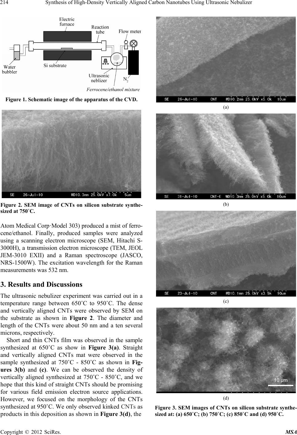 Synthesis of High-Density Vertically Aligned Carbon Nanotubes Using Ultrasonic Nebulizer 214 Figure 1. Schematic image of the apparatus of the CVD. Figure 2. SEM image of CNTs on silicon substrate synthe- sized at 750˚C. Atom Medical Corp·Model 303) produced a mist of ferro- cene/ethanol. Finally, produced samples were analyzed using a scanning electron microscope (SEM, Hitachi S- 3000H), a transmission electron microscope (TEM, JEOL JEM-3010 EXII) and a Raman spectroscope (JASCO, NRS-1500W). The excitation wavelength for the Raman measurement s was 532 nm. 3. Results and Discussions The ultrasonic nebulizer experiment was carried out in a temperature range between 650˚C to 950˚C. The dense and vertically aligned CNTs were observed by SEM on the substrate as shown in Figure 2. The diameter and length of the CNTs were about 50 nm and a ten several microns, respectively. Short and thin CNTs film was observed in the sample synthesized at 650˚C as show in Figure 3(a). Straight and vertically aligned CNTs mat were observed in the sample synthesized at 750˚C - 850˚C as shown in Fig- ures 3(b) and (c). We can be observed the density of vertically aligned synthesized at 750˚C - 850˚C, and we hope that this kind of straight CNTs should be promising for various field emission electron source applications. However, we focused on the morphology of the CNTs synthesized at 950˚C. We only observed kinked CNTs as products in this deposition as shown in Figure 3(d), the (a) (b) (c) 10 µm (d) Figure 3. SEM images of CNTs on silicon substrate synthe- sized at: (a) 650˚C; (b) 750˚C; (c) 850˚C and (d) 950˚C. Copyright © 2012 SciRes. MSA 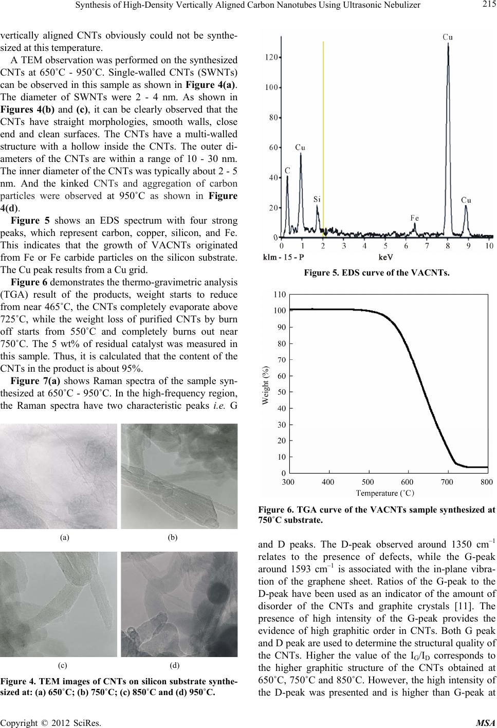 Synthesis of High-Density Vertically Aligned Carbon Nanotubes Using Ultrasonic Nebulizer 215 vertically aligned CNTs obviously could not be synthe- sized at this temperature. A TEM observation was performed on the synthesized CNTs at 650˚C - 950˚C. Single-walled CNTs (SWNTs) can be observed in this sample as shown in Figure 4(a). The diameter of SWNTs were 2 - 4 nm. As shown in Figures 4(b) and (c), it can be clearly observed that the CNTs have straight morphologies, smooth walls, close end and clean surfaces. The CNTs have a multi-walled structure with a hollow inside the CNTs. The outer di- ameters of the CNTs are within a range of 10 - 30 nm. The inner diameter of the CNTs was typically about 2 - 5 nm. And the kinked CNTs and aggregation of carbon particles were observed at 950˚C as shown in Figure 4(d). Figure 5 shows an EDS spectrum with four strong peaks, which represent carbon, copper, silicon, and Fe. This indicates that the growth of VACNTs originated from Fe or Fe carbide particles on the silicon substrate. The Cu peak results from a Cu grid. Figure 6 demonstrates the thermo-gravimetric analysis (TGA) result of the products, weight starts to reduce from near 465˚C, the CNTs completely evaporate above 725˚C, while the weight loss of purified CNTs by burn off starts from 550˚C and completely burns out near 750˚C. The 5 wt% of residual catalyst was measured in this sample. Thus, it is calculated that the content of the CNTs in the product is about 95%. Figure 7(a) shows Raman spectra of the sample syn- thesized at 650˚C - 950˚C. In the high-frequency region, the Raman spectra have two characteristic peaks i.e. G (a) (b) (c) (d) Figure 4. TEM images of CNTs on silicon substrate synthe- sized at: (a) 650˚C; (b) 750˚C; (c) 850˚C and (d) 950˚C. Figure 5. EDS curve of the VACNTs. Figure 6. TGA curve of the VACNTs sample synthesized at 750˚C substrate. and D peaks. The D-peak observed around 1350 cm–1 relates to the presence of defects, while the G-peak around 1593 cm–1 is associated with the in-plane vibra- tion of the graphene sheet. Ratios of the G-peak to the D-peak have been used as an indicator of the amount of disorder of the CNTs and graphite crystals [11]. The presence of high intensity of the G-peak provides the evidence of high graphitic order in CNTs. Both G peak and D peak are used to determine th e structural quality of the CNTs. Higher the value of the IG/ID corresponds to the higher graphitic structure of the CNTs obtained at 650˚C, 750˚C and 850˚C. However, the high intensity of the D-peak was presented and is higher than G-peak at Copyright © 2012 SciRes. MSA 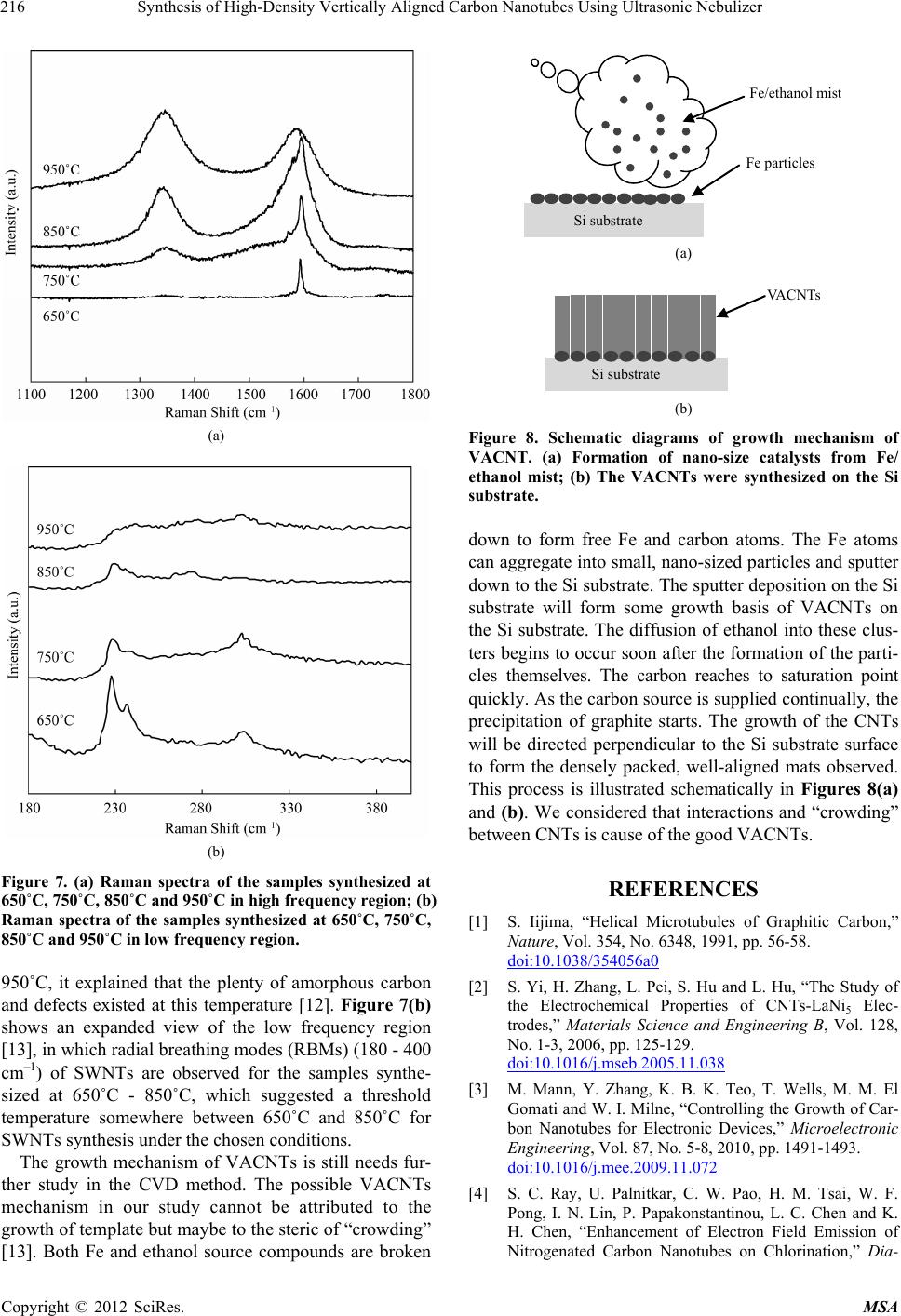 Synthesis of High-Density Vertically Aligned Carbon Nanotubes Using Ultrasonic Nebulizer 216 (a) (b) Figure 7. (a) Raman spectra of the samples synthesized at 650˚C, 750˚C, 850˚C and 950˚C in high frequenc y region; (b) Raman spectra of the samples synthesized at 650˚C, 750˚C, 850˚C and 950˚C in low frequency r e gion. 950˚C, it explained that the plenty of amorphous carbon and defects existed at this temperature [12]. Figure 7(b) shows an expanded view of the low frequency region [13], in which radial breathing modes (RBMs) (180 - 400 cm–1) of SWNTs are observed for the samples synthe- sized at 650˚C - 850˚C, which suggested a threshold temperature somewhere between 650˚C and 850˚C for SWNTs synthesis under the chosen conditions. The growth mechanism of VACNTs is still needs fur- ther study in the CVD method. The possible VACNTs mechanism in our study cannot be attributed to the growth of template bu t maybe to the steric of “crowding ” [13]. Both Fe and ethanol source compounds are broken Fe particles Fe/ethanol mist Si substrate (a) Si substrate VACNTs (b) Figure 8. Schematic diagrams of growth mechanism of VACNT. (a) Formation of nano-size catalysts from Fe/ ethanol mist; (b) The VACNTs were synthesized on the Si substrate. down to form free Fe and carbon atoms. The Fe atoms can aggregate into small, nano-sized particles and sputter down to the Si substrate. The sputter deposition on the Si substrate will form some growth basis of VACNTs on the Si substrate. The diffusion of ethanol into these clus- ters begins to occur soon after the formation of the parti- cles themselves. The carbon reaches to saturation point quickly. As the carbon source is supp lied continually, th e precipitation of graphite starts. The growth of the CNTs will be directed perpendicular to the Si substrate surface to form the densely packed, well-aligned mats observed. This process is illustrated schematically in Figures 8(a) and (b). We considered that interactions and “crowding” between CNTs is cause of the good VACNTs. REFERENCES [1] S. Iijima, “Helical Microtubules of Graphitic Carbon,” Nature, Vol. 354, No. 6348, 1991, pp. 56-58. doi:10.1038/354056a0 [2] S. Yi, H. Zhang, L. Pei, S. Hu and L. Hu, “The Study of the Electrochemical Properties of CNTs-LaNi5 Elec- trodes,” Materials Science and Engineering B, Vol. 128, No. 1-3, 2006, pp. 125-129. doi:10.1016/j.mseb.2005.11.038 [3] M. Mann, Y. Zhang, K. B. K. Teo, T. Wells, M. M. El Gomati and W. I. Milne, “Controlling the Growth of Car- bon Nanotubes for Electronic Devices,” Microelectronic Engineering, Vol. 87, No. 5-8, 2010, pp. 1491-1493. doi:10.1016/j.mee.2009.11.072 [4] S. C. Ray, U. Palnitkar, C. W. Pao, H. M. Tsai, W. F. Pong, I. N. Lin, P. Papakonstantinou, L. C. Chen and K. H. Chen, “Enhancement of Electron Field Emission of Nitrogenated Carbon Nanotubes on Chlorination,” Dia- Copyright © 2012 SciRes. MSA  Synthesis of High-Density Vertically Aligned Carbon Nanotubes Using Ultrasonic Nebulizer Copyright © 2012 SciRes. MSA 217 mond and Related Materials, Vol. 18, No. 2-3, 2009, pp. 457-460. doi:10.1016/j.diamond.2008.07.016 [5] E. Titus, G. Cabral, J. C. Madaleno, V. F. Neto, T. Sho- kuhfar, W. J. Blau, P. R. Babu, D. S. Misra and J. Gracio, “Synthesis of Highly Oriented Carbon Nanotube Thin Films by Nickel Functionalisation,” Diamond and Related Materials, Vol. 16, No. 4-7, 2007, pp. 1195-1199. doi:10.1016/j.diamond.2006.11.033 [6] N. T. Hong, K. H. Koh, N. T. T. Tam, P. N. Minh, P. H. Khoi and S. Lee, “Combined Model for Growing Mecha- nism of Carbon Nanotubes Using HFCVD: Effect of Temperature and Molecule Gas Diffusion,” Thin Solid Films, Vol. 517, No. 12, 2009, pp. 3562-3565. doi:10.1016/j.tsf.2009.01.066 [7] W. I. Milne, K. B. K. Teo, M. Chhowalla, G. A. J. Amaratunga, S. B. Lee, D. G. Hasko, H. Ahmed, O. Gro- ening, P. Legagneux, L. Gangloff, J. P. Schnell, G. Pirio, D. Pribat, M. Castignolles, A. Loiseau, V. Semet and V. T. Binh, “Electrical and Field Emission Investigation of Individual Carbon Nanotubes from Plasma Enhanced Chemical Vapour Deposition,” Diamond and Related Ma- terials, Vol. 12, No. 3-7, 2003, pp. 422-428. [8] C. Chiu, T. Tsai, N. Tai and C. Lee, “Synthesis of Ultra Long Vertically Aligned Carbon Nanotubes Using the Rapid Heating and Cooling System in the Thermal Chemical Vapor Deposition Process,” Surface and Coatings Tech- nology, Vol. 200, No. 8, 2006, pp. 3215-3219. doi:10.1016/j.surfcoat.2005.07.016 [9] R. A. Afre, T. Soga, T. Jimbo, M. Kumar, Y. Ando, M. Sharon, P. R. Somani and M. Umno, “Carbon Nanotubes by Spray Pyrolysis of Turpentine Oil at Different Tem- peratures and Their Studies,” Microporous and Mesopor- ous Materials, Vol. 96, No. 1-3, 2006, pp. 184-190. doi:10.1016/j.micromeso.2006.06.036 [10] R. A. Afre, T. Soga, T. Jimbo, M. Kumar, Y. Ando and M. Sharon, “Growth of Vertically Aligned Carbon Nano- tubes on Silicon and Quartz Substrate by Spray Pyrolysis of a Natural Precursor: Turpentine Oil,” Chemical Phys- ics Letters, Vol. 414, No. 1-3, 2005, pp. 6-10. doi:10.1016/j.cplett.2005.08.040 [11] P. H. Tan, S. L. Zhang, K. T. Yue, F. M. Huang, Z. J. Shi, X. H. Zhou and Z. N. Gu, “Comparative Raman Study of Carbon Nanotubes Prepared by D.C. Arc Discharge and Catalytic Me thods,” Journal of Raman Spectroscopy, Vol. 28, No. 5, 1997, pp. 369-372. doi:10.1002/(SICI)1097-4555(199705)28:5<369::AID-JR S107>3.0.CO;2-X [12] M. S. Dresselhaus, G. Dresselhaus, A. Jorio, A. G. S. Fil ho and R. Saito, “Raman Spectroscopy on Isolated Single Wall Carbon Nanotubes,” Carbon, Vol. 40, No. 12, 2002, pp. 2043-2061. doi:10.1016/S0008-6223(02)00066-0 [13] P. J. Cao, Y. S. Gu, H. W. Liu, F. Shen, Y. G. Wang, Q. F. Zhang, J. L. Wu and H. J. Gao, “High Density Aligned Carbon Nanotubes with Uniform Diameters,” Journal of Materials Research, Vol. 18, No. 7, 2003, pp. 7-14. doi:10.1557/JMR.2003.0231 |