

Paper Menu >>
Journal Menu >>
 Open Journal of Applied Sciences, 2012, 2, 28-34 doi:10.4236/ojapps.2012.21003 Published Online March 2012 (http://www.SciRP.org/journal/ojapps) On Laminar Flow in Microfabricated Channels with Partial Semi-Circular Profiles William J. Federspiel,2,3,4, Isabella Valenti1,2 1Medical Devices Laboratory, McGowan Institute for Regenerative Medicine, University of Pittsburgh, Pittsburgh, USA 2Department of Bioengineering, University of Pittsburgh, Pittsburgh, USA 3Department of Chemical Engineering, University of Pittsburgh, Pittsburgh, USA 4Department of Critical Care Medicine, University of Pittsburgh, Pittsburgh, USA Email: [email protected] Received January 18, 2012; revised February 17, 2012; accepted April February 27, 2012 ABSTRACT Soft and hard micromachining techniques used to develop microfluidic devices can yield microchannels of many dif- ferent cross-sectional profiles. For semi-circular microchannels, these techniques often produce only partial semicircu- lar (PSC) cross-sections. This study investigated fully developed laminar flow in PSC microchannels as a function of a circularity index, , defined as the ratio of the radiuses along the curved and flat surfaces of the PSC profile. A correc- tion factor, K, to the Hagen-Poiseuille relation was determined and was well-fitted by the power-law relationship 2.56 5.299K . Actual correction factors were compared to estimates based on several hydraulic models for flow in mi- crochannels of arbitrary cross-section, as well as the half-ellipsoid cross-section. The level of wall shear stress, when nor- malized by the pressure drop per unit length, increased approximately linearly with increase in the circularity index, . Keywords: Hagen-Poiseuille Flow; Poiseuille Flow; Flow Resistance; Wall Shear Stress 1. Introduction The trend toward miniaturization that has been driven by advances in fabrication processes derived from micro- electromechanical systems (MEMs) and other microsys- tem technologies has led to microfluidic devices for use in numerous chemical, biological and medical applications. Microfluidics refers to devices for accommodating and controlling flow through microchannels with cross-sec- tional scales of 10 - 100 microns. For many traditional applications, microchannels are fabricated on silicon or quartz substrates using photolithographic methods derived directly from MEMs processes. Whitesides and coworkers extended these “hard” microfabrication techniques into the novel realm of soft lithography to create microchan- nels and other microfluidic devices in elastomeric materi- als such as polydimethylsiloxane (PDMS), principally with advantages in biological and biomedical applications [1]. The processes underlying hard and soft microfabrica- tion allow for different microchannel shapes tailored to specific applications. While rectangular microchannels are ubiquitous, the second most common microchannel geometry may be the semi-circular profile, which occurs naturally in hard micromachining with isotropic etching in the photolithographic steps [2]. In soft lithography, plasma etching can also be tailored to provide rounded corners to silicon negative masters, that then yield elas- tomeric microchannels with semi-circular profiles after spin coating [3,4]. The rounded edges of semicircular profiles help promote cell seeding and proliferation in microfluidic devices developed for tissue engineering [3]. Recent studies that have developed microchannels with semi-circular profiles include an analysis of shear stress effects on endothelial cells in curved microvessels [5], the evaluation of micromachined flow cytometers with inte- grated optics [6,7], the creation of a novel magnetohy- drodynamic micropump [8], and studies of microfluidic devices for capillary electrophoresis [9]. Our own group recently developed biohybrid artificial lung modules with semi-circular endothelialized blood microchannels subja- cent to rectangular gas microchannels [10]. The semi-circular microchannels that are fabricated using hard or soft micromachining can best be charac- terized as partial semi-circular (PSC) microchannels, in which the “radius” to the curved-side is appreciably less than the “radius” along the flat-side. Figure 1(a) displays an SEM image of the typical PSC cross-section obtained using soft-lithography from our work on biohybrid artifi- cial lung modules [10], while Figure 1(b) shows an SEM image of a PSC microchannel developed using hard- micromachining for a microfluidic capillary electropho- resis device [9]. A circularity index, , can be defined as the ratio of the radius to the curved-side relative to that Copyright © 2012 SciRes. OJAppS 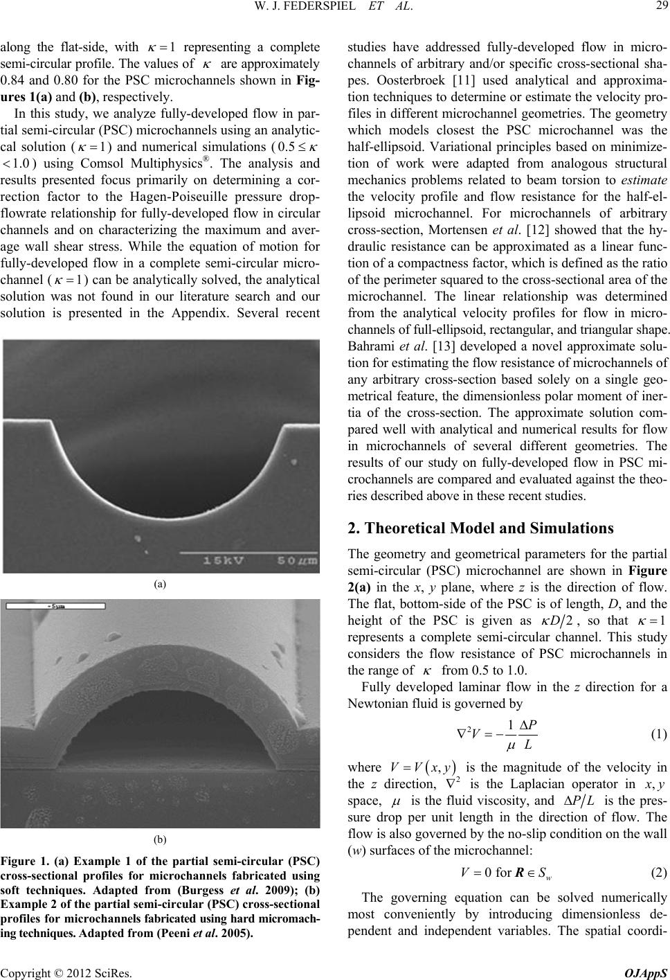 W. J. FEDERSPIEL ET AL. 29 along the flat-side, with representing a complete semi-circular profile. The values of are approximately 0.84 and 0.80 for the PSC microchannels shown in Fig- ures 1(a) and (b), respectively. 1 In this study, we analyze fully-developed flow in par- tial semi-circular (PSC) microchannels using an analytic- cal solution () and numerical simulations ( 1 0.5 ) using Comsol Multiphysics®. The analysis and results presented focus primarily on determining a cor- rection factor to the Hagen-Poiseuille pressure drop- flowrate relationship for fully-developed flow in circular channels and on characterizing the maximum and aver- age wall shear stress. While the equation of motion for fully-developed flow in a complete semi-circular micro- channel () can be analytically solved, the analytical solution was not found in our literature search and our solution is presented in the Appendix. Several recent 1.0 1 (a) (b) Figure 1. (a) Example 1 of the partial semi-circular (PSC) cross-sectional profiles for microchannels fabricated using soft techniques. Adapted from (Burgess et al. 2009); (b) Example 2 of the partial semi-circular (PSC) cross-sectional profiles for microchannels fabricated using hard micromach- ing techniques. Adapted from (Peeni et al. 2005). studies have addressed fully-developed flow in micro- channels of arbitrary and/or specific cross-sectional sha- pes. Oosterbroek [11] used analytical and approxima- tion techniques to determine or estimate the velocity pro- files in different microchannel geometries. The geometry which models closest the PSC microchannel was the half-ellipsoid. Variational principles based on minimize- tion of work were adapted from analogous structural mechanics problems related to beam torsion to estimate the velocity profile and flow resistance for the half-el- lipsoid microchannel. For microchannels of arbitrary cross-section, Mortensen et al. [12] showed that the hy- draulic resistance can be approximated as a linear func- tion of a compactness factor, which is defined as the ratio of the perimeter squared to the cross-sectional area of the microchannel. The linear relationship was determined from the analytical velocity profiles for flow in micro- channels of full-ellipsoid, rectangular, and triangular shape. Bahrami et al. [13] developed a novel approximate solu- tion for estimating the flow resistance of microchannels of any arbitrary cross-section based solely on a single geo- metrical feature, the dimensionless polar moment of iner- tia of the cross-section. The approximate solution com- pared well with analytical and numerical results for flow in microchannels of several different geometries. The results of our study on fully-developed flow in PSC mi- crochannels are compared and evaluated against the theo- ries described above in these recent studies. 2. Theoretical Model and Simulations The geometry and geometrical parameters for the partial semi-circular (PSC) microchannel are shown in Figure 2(a) in the x, y plane, where z is the direction of flow. The flat, bottom-side of the PSC is of length, D, and the height of the PSC is given as 2D , so that 1 represents a complete semi-circular channel. This study considers the flow resistance of PSC microchannels in the range of from 0.5 to 1.0. Fully developed laminar flow in the z direction for a Newtonian fluid is governed by 21P VL (1) where ,VVxy 2 is the magnitude of the velocity in the z direction, is the Laplacian operator in , x y space, is the fluid viscosity, and PL is the pres- sure drop per unit length in the direction of flow. The flow is also governed by the no-slip condition on the wall (w) surfaces of the microchannel: 0 for w VS R (2) The governing equation can be solved numerically most conveniently by introducing dimensionless de- pendent and independent variables. The spatial coordi- Copyright © 2012 SciRes. OJAppS  W. J. FEDERSPIEL ET AL. 30 nates (, x y) are scaled by the flat surface width, D, while the flow velocity is scaled according to: 2 DP UV L (3) The resulting dimensionless equation of motion is given by: 21U (4) where is the dimensionless Laplacian operator on the domain shown in Figure 2(b). 2 The no-slip boundary condition requires 0U on the surfaces in Figure 2(b) . Comsol Multiphysics® Version 3.4 was used to nu- merically solve Equation (4), subject to its boundary con- dition, on the dimensionless domain (Figure 2(b)) using the Poisson equation solver in the basic multiphysics module of Comsol. The solution for the dimensionless flow velocity was integrated over the dimensionless do- main (subdomain integration in Comsol) to obtain a “correction factor” to the Hagen-Poiseuille relation for laminar flow in a circular conduit. The correction factor, K, is defined from the integrated dimensionless velocity for convenience as (a) (b) Figure 2. (a) Schematic illustrating the cross-sectional ge- ometry of the PSC microchannel in dimensional forms. The circularity index denotes the departure from a full semi- circular channel (); (b) Schematic illustrating the cross-sectional geometry of the PSC microchannel in di- mensionless forms. The circularity index denotes the de- parture from a full semi-circular channel (). 1 1 1 π d128 A UA K (5) where d A and A indicate integration over the di- mensionless domain (Figure 2(b)). With this definition, transforming Equation (5) back into dimensional form yields: 4 128 π L PK Q D (6) where Q is the volumetric flowrate through the channel. Thus, the correction factor K represents the proportion by which the flow resistance (PQ ) is increased in a PSC microchannel compared to a circular duct of diameter, D. Also of interest is the shear stress exerted on the wall by the flowing fluid. The wall shear stress is the z com- ponent of the fluid stress vector exerted on the wall: n, where is the stress tensor, given for a Newtonian fluid by t VV, and n is a unit normal vector at the wall directed into the domain. Applying these relationships and noting thV at Vk by , the wall shear stress in the PSC microchannel is given wV n (7) which can be determined in a normalized form directly from the numerical solution by computing the normal derivative of the dimensionless velocity at the wall: wU DPL n (8) 3. Results and Discussion 3.1. Hagen-Poiseuille Correction Factor Fully developed laminar flow in partial semi-circular (PSC) microchannels was numerically simulated using Comsol Multiphysics®. The “partial” nature of the PSC microchannel was specified by the dimensionless pa- rameter, wherein the height of the PSC microchannel was 2D , with D being the diameter or width of the flat-side of the PSC microchannel. Laminar flow was characterized over the range . Simulations were performed using dimensionless variables with the 0.5 1.0 velocity (V) normalized according to 2 DP VL , where is fluid viscosity and PL is the pressure drop per unit length in the channel. Figure 3 shows the contours of the normalized velocity field in a PSC mi- crochannel with 0.5 . The pressure drop and flowrate relationship for PSC microchannels was characterized by introducing a cor- rection factor, K, to the Hagen-Poiseuille relation (see Equation (6)), in which K represents the proportion by Copyright © 2012 SciRes. OJAppS  W. J. FEDERSPIEL ET AL. 31 Figure 3. Normalized velocity contours for fully-developed laminar flow in a PSC microchannel for . .05 which the flow resistance is increased in a PSC micro- channel compared to a circular duct of the same diameter. The flow correction factor increased by 6-fold as decreased from (complete semi-circular micro- channel) to ( Figure 4(a)). 1.0 0.5 In this range the correction factor was well fit by the power-law relation: 2.56 5.299K . For the complete semi-circular microchannel (1.0 ), the correction factor computed from the simulations (5.279) was in agreement with that from the analytical solution (5.279) for a semi-circular microchannel (see Appendix). Figure 4(b) displays the correction factor plotted against the microchannel compactness factor, C. Mortensen et al. [12] developed a theoretical analysis showing that for microchannels of arbitrary cross-section, the hydraulic resistance varies approximately linearly with a compact- ness factor defined by: 2 P C A (9) in which P and A are the microchannel perimeter and cross-sectional area, respectively. In the range of the cir- cularity index () studied here, the correction factor did follow the linear relationship: K = 3.517C – 55.35 with an value of 0.98. 2 R The Hagen-Poiseuille correction factor can also be compared with predictions based on several hydraulic models for flow in arbitrary microchannels. The simplest hydraulic model would be based on using the hydraulic diameter, 4 h DAP, in the Hagen-Poiseuille relation. The correction factor is then given by 44 D h. Table 1 indicates that the hydraulic diameter model significantly over-predicts the correction factor by 36% to 75% in the range of studied. D Bahrami et al. [13] (ref: doi:10.1016/j.ijheatmasstrans fer.2006.12.019) developed a novel approach for esti- mating the flow resistance of microchannels of any arbi- trary cross-section. Their analysis introduces the dimen- Table 1. Comparison of actual and predicted Hagen- Poiseuille correction factors. act K 1 hd K 2 pmi K 3 s e K 4 0.5 32.21 56.37 31.86 34.66 0.6 19.46 31.19 19.19 20.74 0.7 12.87 19.37 12.64 13.56 0.8 9.107 13.09 8.905 9.479 0.9 6.787 9.447 6.610 6.969 1 5.279 7.174 5.117 5.333 (a) (b) Figure 4. (a) Correction factor, K, for the Hagen-Poiseuille relation as a function of circularity index ; (b) Correc- tion factor, K, for the Hagen-Poiseuille relation as a func- tion of the compactness factor C. sionless polar moment of inertia, * p I , computed for the microchannel geometry: 22 2 1d pcc A I xxy A A y (10) in which the dimensionless coordinates and cross-sec- tional area (denoted with asterisks) are scaled by the same dimension. (Note: Comsol automatically calculates Copyright © 2012 SciRes. OJAppS  W. J. FEDERSPIEL ET AL. 32 the polar moment of inertia and all other pertinent geo- metric parameters for any defined domain.) Applying their analysis to determine the Hagen-Poiseuille correc- tion factor yields: 3 2 1π 8 p I K A (11) in which the dimension used to normalize for length is that used in the Hagen-Poiseuille relation itself. Table 1 indicates that Equation (11) provides a very good esti- mate for the correction factor of PSC microchannels, underestimating the correction factor by only 1.1% at to 3.1% at . 0.5 1.0 An approximate model for the cross-sectional profile a PSC microchannel is a half-ellipsoid. While an analytical solution to the equation of fluid motion does not exist for the half-ellipsoid, Oosterbroek used a variational approach based on minimization of work, adapted from the analo- gous structural mechanics problem of beam torsion, to approximate the velocity profile and flow resistance for half-ellipsoid microchannels [11]. The approximate re- sistance, R, of a half-ellipsoid microchannel was deter- mined as 22 33 32 3 π3 La b Rab (12) where a and b are the major and minor axes of the half-ellipsoid. Since ba approximates the circularity index, , Equation (12) yields the Hagen-Poiseuille correction factor: 2 3 3 43 K (13) Table 1 indicates that the correction factor based on the half-ellipsoid is also a good estimate for the correction factor for PSC microchannels, in this case over-estimating the correction factor most at small : 7.6% at 0.5 , and improving to a 1.0 % over-estimate at . 1.0 3.2. Wall Shear Stress Distribution The wall shear stress associated with fully developed laminar flow in PSC microchannels would also be of interest in many applications, especially biomedical ap- plications involving cells. The wall shear stress, w , computed directly from the dimensionless flow field is normalized according to wP DL . Figure 5 shows the variation of the normalized wall shear stress on the flat and curved surfaces of a PSC microchannel for . As would be anticipated, the maximum shear stress occurs in the middle of the flat surface for PSC microchannels. 0.5 The maximum and average values of the normalized Figure 5. Distribution of the normalized wall shear stress, along the flat and curved surfaces of a PSC microchannel for .05 . Figure 6. The linear variation in the maximum and average normalized wall shear stress with the circularity index . wall shear stress varied approximately linearly with , as shown in Figure 6. The linear correlations for the maximum and average normalized wall shear stresses are: m and (re- spectively). The shear stress decreased by a factor of 0.57 as 0.1820.032 0.122 0.031 a decreased from unity to . 0.5 This decrease occurs because the shear stress was nor- malized by the pressure drop per unit length in the mi- crochannels. For a given flowrate, the pressure drop per unit length increases about 6-fold as decreases from 1.0 to 0.5 (see Figure 4(a)). Accordingly, for a given flowrate the shear stress would increase by ap- proximately 3.4-fold as decreases from 1.0 to 0.5 . For 1.0 the normalized maximum shear stress from the simulations (0.212) was in agreement with that from the analytical solution (0.212) for a semi-circu- lar channel (Appendix). Copyright © 2012 SciRes. OJAppS  W. J. FEDERSPIEL ET AL. Copyright © 2012 SciRes. OJAppS 33 4. Conclusions 1) For fully developed laminar flow in partial semi-cir- cular (PSC) microchannels, the correction factor, K, to the Hagen-Poiseuille relationship is well fitted by the power law relation: 2.56 5.299K in the range of , where is an index of circularity relat- 0.5 1.0 ing the radius of the curved surface, 1 2D , to that of the flat surface, 2D. 2) The correction factor can be predicted within 3% by a novel relationship developed for microchannels of ar- bitrary cross-section, which accounts for the shape of the cross-sectional profile using only the dimensionless polar moment of inertia for the profile. 3) The normalized wall shear stress, wP DL increases approximately linearly with the circularity index . The maximum shear stress occurs at the center of the flat surface. The maximum (m) and average (a) normal- ized wall shear stresses are given and . 0.1820.032 m 0.122 0.031 a 5. Acknowledgements The work presented in this publication was made possi- ble by grants HL70051 and HL080926 from the National Heart, Lung, and Blood Institute at the National Institutes of Health. The contents are solely the responsibility of the authors and do not necessarily represent the official views of the National Heart, Lung, and Blood Institute or National Institutes of Health. We would like to recognize the University of Pittsburgh’s McGowan Institute for Regenerative Medicine for support of this study. REFERENCES [1] G. M. Whitesides and S. K. Sia, “Microfluidic Devices Fabricated in Poly(Dimethylsiloxane) for Biological Studies,” Electropheresis, Vol. 24, No. 21, 2003, pp. 3563-3576. doi:10.1002/elps.200305584 [2] B. Ziaie, A. Baldi, M. Lei, Y. Gu and R. A. Siegel, “Hard and Soft Micromachining for BioMEMS: Review of Techniques and Examples of Applications in Microflu- idics and Drug Delivery,” Advanced Drug Delivery Re- views, Vol. 56, No. 2, 2004, pp. 145-172. doi:10.1016/jaddr.2003.09.001 [3] J. T. Borenstein, H. Terai, K. R. King, E. J. Weinberg, M. R. Kaazempur-Mofrad and J. P. Vacanti, “Microfabrica- tion Technology for Vascularized Tissue Engineering,” Biomedical Microdevices, Vol. 4, No. 3, 2002, pp. 167- 175. doi:10.1023/A:1016040212127 [4] M. Shin, M. K. Matsuda, O, Ishii, H. Terai, M. Kaazem- pur-Mofrad, J. Borenstein, M. Detmar and J. P. Vacanti, “Endothelialized Networks with a Vascular Geometry in Microfabricated Poly(Dimethyl Siloxane),” Biomedical Microdevices, Vol. 6, No. 4, 2004, pp. 269-278. [5] M. D. S. Frame, G. B. Chapman, Y. Makino and I. H. Sarelius, “Shear Stress Gradient over Endothelial Cells in a Curved Microchannel System,” Biorheology, Vol. 35, No. 4, 1998, pp. 245-261. doi:10.1016/S0006-355X(99)80009-2 [6] O. L. Li, Y. L. Tong, Z. G. Chen, C. Liu, S. Zhao and J. Y. Mo, “A Glass/PDMS Hybrid Microfluidic Chip Em- bedded with Integrated Electrodes for Contactless Con- ductivity Detection,” Chromatographia, Vol. 68, No. 11, 2008, pp. 1039-1044. doi:10.1365/s10337-008-0808-y [7] C. H. Lin and G. B. Lee, “Micromachined Flow Cytome- ters with Embedded Etched Optic Fibers for Optical De- tection,” Journal of Micromechanics and Microengineer- ing, Vol. 13, No. 3, 2003, pp. 447-453. doi:10.1088/0960-1317/13/3/315 [8] A. Homsy, S. Koster, J. C. T. Eijkel, A. Van den Berg, F. Lucklum, E. Verpoorte and N. F. de Rooij, “A High Cur- rent Density DC Magnetohydrodynamic (MHD) Micro- pump,” Lap on a Chip, Vol. 5, No. 4, 2005, pp. 466-471. doi:10.1039/b417892k [9] B. A. Peeni, D. B. Conkey, J. P. Barber, R. T. Kelly, M. L. Lee, A. T. Woolley and A. R. Hawkins, “Planar Thin Film Device for Capillary Electrophoresis,” Lap on a Chip, Vol. 5, No. 2, 2005, pp. 501-505. doi:10.1039/b500870k [10] K. Burgess, H. H. Hu, W. Wagner and W. J. Federspiel, “Towards Microfabricated Biohybrid Artificial Lung Modules for Chronic Respiratory Support,” Biomedical Microdevices, Vol. 11, No. 1, 2009, pp. 117-127. doi:10.1159/000331400 [11] E. Oosterbroek, “Modeling, Design and Realization of Microfluidics Components,” Ph.D. Thesis, University of Twente, Enschede, 1999. [12] N. A. Mortensen, F. Okkels and H. Bruus, “Reexamina- tion of Hagen-Poiseuille Flow: Shape Dependence of the Hydraulic Resistance in Microchannels,” Physical Review E, Vol. 71, No. 5, 2005, Article ID: 057301. doi:10.1103/PhysRevE.71.057301 [13] M. Bahrami, M. Yovanovich and R. J. Culham, “A Novel Solution for Pressure Drop in Singly Connected Micro- channels of Arbitrary Cross-Section,” International Jour- nal of Heat and Mass Transfer, Vol. 50, No. 13-14, 2007, pp. 2492-2502. doi:10.1016/j.ijheatmasstransfer.2006.12.019  W. J. FEDERSPIEL ET AL. 34 Appendix The normalized equation of motion can be analytically solved readily for the special case of a semi-circular channel (). Using polar coordinates ( 1.0 ,r ) cen- tered on the flat side of the normalized geometry, the dimensionless equation of motion is: 2 2 11 1 UU r rrrr (A1) with the no-slip boundary conditions: 12, ,0UU r . A separation of variables approach can be undertaken after the substitution: ,π0Ur 2 1 ,, cos2 4 Ur Wrr 1 (A2) which leads to Laplace’s equation for ,Wr : 2 2 11 0 WW r rrr r with the same no-slip conditions as for U with the excep- tion 11 ,cos2 216 W 1 . A straight-forward separation of variables solution to Equation (A3) can be performed resulting in a series so- lution for ,Wr . Substituting that solution into Equa- tion (A2) results in the normalized velocity profile for a semi-circular channel: 2 21 2 1 1 ,cos21 4 sin 21 1 2 2π212123 n n n Ur r rn nnn (A4) The integrals and derivatives leading to the Hagen- Poiseuille correction factor and normalized wall shear stress are straightforward and hence are not provided here. (A3) Copyright © 2012 SciRes. OJAppS |