

Paper Menu >>
Journal Menu >>
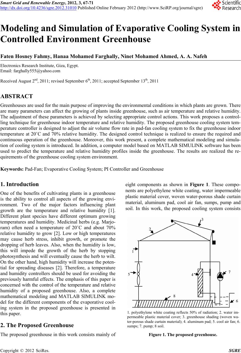 Smart Grid and Renewable Energy, 2012, 3, 67-71 http://dx.doi.org/10.4236/sgre.2012.31010 Published Online February 2012 (http://www.SciRP.org/journal/sgre) 67 Modeling and Simulation of Evaporative Cooling System i n Controlled Environment Greenhouse Faten Hosney Fahmy, Hanaa Mohamed Farghally, Ninet Mohamed Ahmed, A. A. Nafeh Electronics Research Institute, Giza, Egypt. Email: [email protected] Received August 2nd, 2011; revised September 6th, 2011; accepted September 13th, 2011 ABSTRACT Greenhouses are used for the main purpose of improving the environmental conditions in which plants are grown. There are many parameters can affect the growing of plants inside greenhouse, such as air temperature and relative humidity. The adjustment of these parameters is achieved by selecting appropriate control actions. This work proposes a control- ling technique for greenhouse indoor temperature and relative humidity. The proposed greenhouse cooling system tem- perature controller is designed to adjust the air volume flow rate in pad-fan cooling system to fix the greenhouse indoor temperature at 20˚C and 70% relative humidity. The designed control technique is realized to ensure the required and continuous operation of the greenhouse. Moreover, this work present, a complete mathematical modeling and simula- tion of cooling system is introduced. In addition, a computer model based on MATLAB SIMULINK software has been used to predict the temperature and relative humidity profiles inside the greenhouse. The results are realized the re- quirements of the greenhouse cooling system environment. Keywords: Pad-Fan; Evaporative Cooling System; PI Controller and Greenhouse 1. Introduction One of the benefits of cultivating plants in a greenhouse is the ability to control all aspects of the growing envi- ronment. Two of the major factors influencing plant growth are the temperature and relative humidity [1]. Different plant species have different optimum growing temperatures and humidity. Medicinal herbs (e.g. Marjo- ram) often need a temperature of 20˚C and about 70% relative humidity to grow [2]. Low or high temperatures may cause herb stress, inhibit growth, or promote the dropping of herb leaves. Also, when the humidity is low, this will impede the growth of the herb by stopping photosynthesis and will eventually cause the herb to wilt. On the other hand, high humidity will increase the poten- tial for spreading diseases [2]. Therefore, a temperature and humidity controllers should be used for avoiding the previously harmful effects. The emphasis of this paper is concerned with the control of the temperature and relative humidity of a proposed greenhouse. Also, a complete mathematical modeling and MATLAB SIMULINK mo- del for the different components of the evaporative cool- ing system in the proposed greenhouse is presented in this paper. 2. The Proposed Greenhouse The proposed greenhouse in this work consists mainly of eight components as shown in Figure 1. These compo- nents are polyethylene white coating, water impermeable plastic material cover, woven water-porous shade curtain material, aluminum pad, cool air fan, sumps, pump and soil. In this work, the proposed cooling system consists 1. polyethylene white coating reflects 50% of radiation; 2. water im- permeable plastic material cover; 3. greenhouse shading (woven wa- ter-porous shade curtain material); 4. aluminum pad; 5. cool air fan; 6. sumps; 7. pump; 8 soil. Figure 1. The proposed greenhouse. Copyright © 2012 SciRes. SGRE 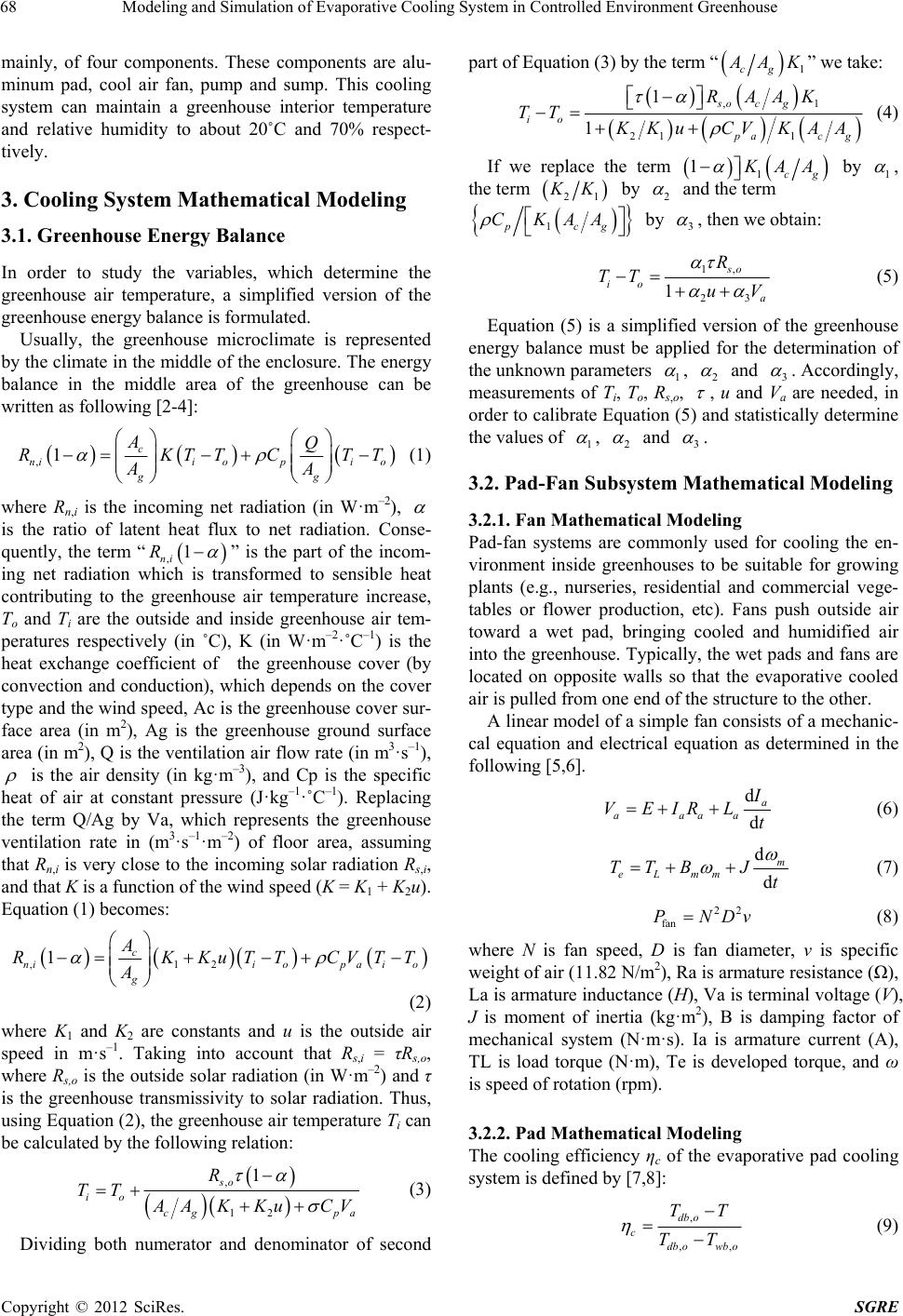 Modeling and Simulation of Evaporative Cooling System in Controlled Environment Greenhouse 68 mainly, of four components. These components are alu- minum pad, cool air fan, pump and sump. This cooling system can maintain a greenhouse interior temperature and relative humidity to about 20˚C and 70% respect- tively. 3. Cooling System Mathematical Modeling 3.1. Greenhouse Energy Balance In order to study the variables, which determine the greenhouse air temperature, a simplified version of the greenhouse energy balance is formulated. Usually, the greenhouse microclimate is represented by the climate in the middle of the enclosure. The energy balance in the middle area of the greenhouse can be written as following [2-4]: ,1c nii opi o gg AQ RKTTC AA TT (1) where Rn,i is the incoming net radiation (in W·m–2), is the ratio of latent heat flux to net radiation. Conse- quently, the term “ ,1 ni R ” is the part of the incom- ing net radiation which is transformed to sensible heat contributing to the greenhouse air temperature increase, To and Ti are the outside and inside greenhouse air tem- peratures respectively (in ˚C), K (in W·m–2·˚C–1) is the heat exchange coefficient of the greenhouse cover (by convection and conduction), which depends on the cover type and the wind speed, Ac is the greenhouse cover sur- face area (in m2), Ag is the greenhouse ground surface area (in m2), Q is the ventilation air flow rate (in m3·s–1), is the air density (in kg·m–3), and Cp is the specific heat of air at constant pressure (J·kg–1·˚C–1). Replacing the term Q/Ag by Va, which represents the greenhouse ventilation rate in (m3·s–1·m–2) of floor area, assuming that Rn,i is very close to the incoming solar radiation Rs,i, and that K is a function of the wind speed (K = K1 + K2u). Equation (1) becomes: ,12 1c niio paio g A RK KuTTCVTT A (2) where K1 and K2 are constants and u is the outside air speed in m·s–1. Taking into account that Rs,i = τRs,o, where Rs,o is the outside solar radiation (in W·m–2) and τ is the greenhouse transmissivity to solar radiation. Thus, using Equation (2), the greenhouse air temperature Ti can be calculated by the following relation: , 12 1 so io cg pa R TT A AKKu CV (3) Dividing both numerator and denominator of second part of Equation (3) by the term “ 1cg A AK” we take: ,1 21 1 1 1 so c g io p ac RAAK TT g K KuCV KAA (4) If we replace the term 1 1cg K AA by 1 , the term 21 K K by 2 and the term 1pcg CKAA by 3 , then we obtain: 1, 23 1 so io a R TT uV (5) Equation (5) is a simplified version of the greenhouse energy balance must be applied for the determination of the unknown parameters 1 , 2 and 3 . Accordingly, measurements of Ti, To, Rs,o, , u and Va are needed, in order to calibrate Equation (5) and statistically determine the values of 1 , 2 and 3 . 3.2. Pad-Fan Subsystem Mathematical Modeling 3.2.1. Fan Mathematical Modeli ng Pad-fan systems are commonly used for cooling the en- vironment inside greenhouses to be suitable for growing plants (e.g., nurseries, residential and commercial vege- tables or flower production, etc). Fans push outside air toward a wet pad, bringing cooled and humidified air into the greenhouse. Typically, the wet pads and fans are located on opposite walls so that the evaporative cooled air is pulled from one end of the structure to the other. A linear model of a simple fan consists of a mechanic- cal equation and electrical equation as determined in the following [5,6]. d d a aaaa I VEIRL t (6) d d m eLmm TTBJt (7) 22 fan PNDv (8) where N is fan speed, D is fan diameter, v is specific weight of air (11.82 N/m2), Ra is armature resistance (Ω), La is armature inductance (H), Va is terminal voltage (V), J is moment of inertia (kg·m2), B is damping factor of mechanical system (N·m·s). Ia is armature current (A), TL is load torque (N·m), Te is developed torque, and ω is speed of rotation (rpm). 3.2.2. Pad Mathematical Modeli ng The cooling efficiency ηc of the evaporative pad cooling system is defined by [7,8]: , ,, db o c db owb o TT TT (9) Copyright © 2012 SciRes. SGRE 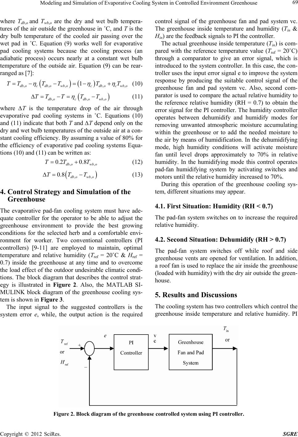 Modeling and Simulation of Evaporative Cooling System in Controlled Environment Greenhouse Copyright © 2012 SciRes. SGRE 69 where Tdb,o and Twb,o are the dry and wet bulb tempera- tures of the air outside the greenhouse in ˚C, and T is the dry bulb temperature of the cooled air passing over the wet pad in ˚C. Equation (9) works well for evaporative pad cooling systems because the cooling process (an adiabatic process) occurs nearly at a constant wet bulb temperature of the outside air. Equation (9) can be rear- ranged as [7]: control signal of the greenhouse fan and pad system vc. The greenhouse inside temperature and humidity (Tin & Hin) are the feedback signals to PI the controller. ,,,, 1 dboc dbowboc dbocwbo TTT TTT , (10) The actual greenhouse inside temperature (Tin) is com- pared with the reference temperature value (Tref = 20˚C) through a comparator to give an error signal, which is introduced to the system controller. In this case, the con- troller uses the input error signal e to improve the system response by producing the suitable control signal of the greenhouse fan and pad system vc. Also, second com- parator is used to compare the actual relative humidity to the reference relative humidity (RH = 0.7) to obtain the error signal for the PI controller. The humidity controller operates between dehumidify and humidify modes for removing unwanted atmospheric moisture accumulating within the greenhouse or to add the needed moisture to the air by means of humidification. In the dehumidifying mode, high humidity conditions will activate moisture fan until level drops approximately to 70% in relative humidity. In the humidifying mode this control operates pad-fan humidifying system by activating switches and motors until the relative humidity increased to 70%. ,,db ocdbowb o TT TTT , , (11) where ∆T is the temperature drop of the air through evaporative pad cooling systems in ˚C. Equations (10) and (11) indicate that both T and ∆T depend only on the dry and wet bulb temperatures of the outside air at a con- stant cooling efficiency. By assuming a value of 80% for the efficiency of evaporative pad cooling systems Equa- tions (10) and (11) can be written as: , 0.2 0.8 db owb o TT T (12) ,, 0.8 db owb o TTT (13) During this operation of the greenhouse cooling sys- tem, different situations may appear. 4. Control Strategy and Simulation of the Greenhouse 4.1. First Situation: Humidity (RH < 0.7) The evaporative pad-fan cooling system must have ade- quate controller for the operator to be able to adjust the greenhouse environment to provide the best growing conditions for the selected herb and a comfortable envi- ronment for worker. Two conventional controllers (PI controllers) [9-11] are employed to maintain, optimal temperature and relative humidity (Tref = 20˚C & Href = 0.7) inside the greenhouse at any time and to overcome the load effect of the outdoor undesirable climatic condi- tions. The block diagram that describes the control strat- egy is illustrated in Figure 2. Also, the MATLAB SI- MULINK block diagram of the greenhouse cooling sys- tem is shown in Figure 3. The pad-fan system switches on to increase the required relative humidity. 4.2. Second Situation: Dehumidify (RH > 0.7) The pad-fan system switches off while roof and side greenhouse vents are opened for ventilation. In addition, a roof fan is used to replace the air inside the greenhouse (loaded with humidity) with the dry air outside the green- house. 5. Results and Discussions The cooling system has two controllers which control the greenhouse inside temperature and relative humidity. PI The input signal to the suggested controllers is the system error e, while, the output action is the required Figure 2. Block diagram of the greenhouse controlled system using PI controller. 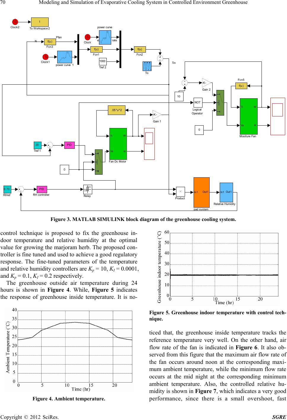 Modeling and Simulation of Evaporative Cooling System in Controlled Environment Greenhouse 70 Tin NPfan volume flow rate pad syst em In1 Out1 Tref 2 1000 Tref 1 20 To Work space2 t To Relay Rela t ive Hum i di t y In1 Out1 RHref 0.70 RH cont rol l er PID Product Mositure Fan Tl Va W Ia Logical Operator NOT Gain 2 -K- Gain 1 -K- Fcn5 f(u ) Fcn3 f(u ) Fcn2 f(u) Fcn1 f(u) .05*u^ 2 Fan Dc Motor Tl Va W Ia 0 10 0 Clock2 Clock1 Clock power cur ve1 power curve PID Figure 3. MATLAB SIMULINK bloc k diagram of the greenhouse cooling system. control technique is proposed to fix the greenhouse in- door temperature and relative humidity at the optimal value for growing the marjoram herb. The proposed con- troller is fine tuned and used to achieve a good regulatory response. The fine-tuned parameters of the temperature and relative humidity controllers are Kp = 10, KI = 0.0001, and Kp = 0.1, KI = 0.2 respectively. The greenhouse outside air temperature during 24 hours is shown in Figure 4. While, Figure 5 indicates the response of greenhouse inside temperature. It is no- Figure 4. Ambient temperature. Figure 5. Greenhouse indoor temperature with control tech- nique. ticed that, the greenhouse inside temperature tracks the reference temperature very well. On the other hand, air flow rate of the fan is indicated in Figure 6. It also ob- served from this figure that the maximum air flow rate of the fan occurs around noon at the corresponding maxi- mum ambient temperature, while the minimum flow rate occurs at the mid night at the corresponding minimum ambient temperature. Also, the controlled relative hu- midity is shown in Figure 7, which indicates a very good performance, since there is a small overshoot, fast Copyright © 2012 SciRes. SGRE 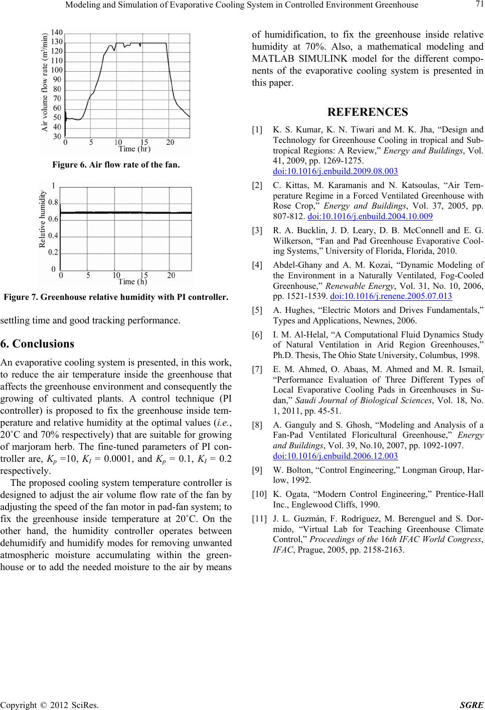 Modeling and Simulation of Evaporative Cooling System in Controlled Environment Greenhouse 71 Figure 6. Air flow rate of the fan. Figure 7. Greenhouse relative humidity with PI controller. settling time and good tracking performance. 6. Conclusions An evaporative cooling system is presented, in this work, to reduce the air temperature inside the greenhouse that affects the greenhouse environment and consequently the growing of cultivated plants. A control technique (PI controller) is proposed to fix the greenhouse inside tem- perature and relative humidity at the optimal values (i.e. , 20˚C and 70% respectively) that are suitable for growing of marjoram herb. The fine-tuned parameters of PI con- troller are, Kp =10, KI = 0.0001, and Kp = 0.1, KI = 0.2 respectively. The proposed cooling system temperature controller is designed to adjust the air volume flow rate of the fan by adjusting the speed of the fan motor in pad-fan system; to fix the greenhouse inside temperature at 20˚C. On the other hand, the humidity controller operates between dehumidify and humidify modes for removing unwanted atmospheric moisture accumulating within the green- house or to add the needed moisture to the air by means of humidification, to fix the greenhouse inside relative humidity at 70%. Also, a mathematical modeling and MATLAB SIMULINK model for the different compo- nents of the evaporative cooling system is presented in this paper. REFERENCES [1] K. S. Kumar, K. N. Tiwari and M. K. Jha, “Design and Technology for Greenhouse Cooling in tropical and Sub- tropical Regions: A Review,” Energy and Buildings, Vol. 41, 2009, pp. 1269-1275. doi:10.1016/j.enbuild.2009.08.003 [2] C. Kittas, M. Karamanis and N. Katsoulas, “Air Tem- perature Regime in a Forced Ventilated Greenhouse with Rose Crop,” Energy and Buildings, Vol. 37, 2005, pp. 807-812. doi:10.1016/j.enbuild.2004.10.009 [3] R. A. Bucklin, J. D. Leary, D. B. McConnell and E. G. Wilkerson, “Fan and Pad Greenhouse Evaporative Cool- ing Systems,” University of Florida, Florida, 2010. [4] Abdel-Ghany and A. M. Kozai, “Dynamic Modeling of the Environment in a Naturally Ventilated, Fog-Cooled Greenhouse,” Renewable Energy, Vol. 31, No. 10, 2006, pp. 1521-1539. doi:10.1016/j.renene.2005.07.013 [5] A. Hughes, “Electric Motors and Drives Fundamentals,” Types and Applications, Newnes, 2006. [6] I. M. Al-Helal, “A Computational Fluid Dynamics Study of Natural Ventilation in Arid Region Greenhouses,” Ph.D. Thesis, The Ohio State University, Columbus, 1998. [7] E. M. Ahmed, O. Abaas, M. Ahmed and M. R. Ismail, “Performance Evaluation of Three Different Types of Local Evaporative Cooling Pads in Greenhouses in Su- dan,” Saudi Journal of Biological Sciences, Vol. 18, No. 1, 2011, pp. 45-51. [8] A. Ganguly and S. Ghosh, “Modeling and Analysis of a Fan-Pad Ventilated Floricultural Greenhouse,” Energy and Buildings, Vol. 39, No.10, 2007, pp. 1092-1097. doi:10.1016/j.enbuild.2006.12.003 [9] W. Bolton, “Control Engineering,” Longman Group, Har- low, 1992. [10] K. Ogata, “Modern Control Engineering,” Prentice-Hall Inc., Englewood Cliffs, 1990. [11] J. L. Guzmán, F. Rodríguez, M. Berenguel and S. Dor- mido, “Virtual Lab for Teaching Greenhouse Climate Control,” Proceedings of the 16th IFAC World Congress, IFAC, Prague, 2005, pp. 2158-2163. Copyright © 2012 SciRes. SGRE |