

Paper Menu >>
Journal Menu >>
 Smart Grid and Renewable Energy, 2012, 3, 56-61 http://dx.doi.org/10.4236/sgre.2012.31008 Published Online February 2012 (http://www.SciRP.org/journal/sgre) Lowering Gasifier Tars and Particulates Using Heated Dololmite Catalyst and a Particulate Filter Christopher O. Akudo, Beatrice G. Terigar, Chandra S. Theegala* Department of Biological and Agricultural Engineering, Louisiana State University, Baton Rouge, USA. Email: *[email protected] Received December 21st, 2011; revised January 31st, 2012; accepted February 7th, 2012 ABSTRACT For this study, a fixed-bed, down-draft gasifier was designed to investigate the effect of a dolomite catalytic bedon tar removal. Pine pellets and wood chips (cypress) were used to produce syngas from the down-draft gasifier. For the gas conditioning, a combination of a heated dolomite (bed temperature at 850˚C for catalytic cracking of tars) and a par- ticulate filter (for particulate removal) was used. Investigation of temperature effects on dolomite activity between 650˚C and 950˚C bed temperatures, showed optimum catalytic efficiency at approximately 850˚C. At the optimum con- ditions, gravimetric tar and particulate concentrations in syngas produced from pine pellets were 0.85 g/Nm3 (±0.16) and 4.75 g/Nm3 (±0.07), respectively before gas condition ing, and 0.09 g/Nm3 (±0.02) and 2.01 g/Nm3 (±0.13), respec- tively after gas conditioning . Syngas fro m wood ch ips con tained 1.63 g/Nm 3 (± 0.45) and 3 .84 g/Nm3 (±1.16) of tars and particulates, respectively before gas cleaning and 0.19 g/Nm3 (±0.02) and 2.27 g/Nm3 (±0.27) tars and particulates, re- spectively after gas conditioning. The combustible portion of the gas constituted carbon monoxide (12% - 14%), hy- drogen (11% - 12%), and methane (~2%). These results suggest that syngas produced from gasification of pine pellets and wood chips in a down-draft biomass gasifier can be effectively cleaned using a heated catalyst bed and a particulate filter. However, the benefits of gas conditioning will be offset by the need to maintain a heated catalyst bed for tar cracking. Keywords: Gasification; Dolomite; Tars; Particulates; Syngas 1. Introduction Biomass gasification is a thermo-chemical process that produces relatively clean and combustible gases through pyrolytic reaction. Depending on the gasifying ag ent (air, steam, oxygen) the raw gas produced at the gasifier exit has different compositions. The most commonly used agent at demonstration and commercial scale is air, with equivalence ratios of 0.2 - 0.3 [1]. By use of air, the flue exit gas contains, on a volumetric basis, about 50% N2, 8% - 20% H2and CO (each) and 2% - 4% CH4, with the remainders being CO2 and H2O [1]. This gas composition is mostly useful only for heat generation and electricity production. The exact gas composition at the gasifier exit in the process depends on other operating variables, and it has been well studied by different authors, at different operating scales and with different gasifiers [2-4]. In ad- dition to these gases, a condensable mixture of organic compounds referred to as tars are formed [5]. Tars are undesirable because of the problems associated with condensation in the downstream processes where they form tar aerosols, and polymerization to form more com- plex structures which can damage internal combustion engines, gas turbines, and other machinery. Therefore, the syngas needs to be cleaned of tars and other solid particles before it can be used in any fuel conversion device. The final gas quality dictates the end use or ap- plication suitabilit y of the generated syngas. There has been extensive research on tar elimination using catalysts that aid in the decomposition of the hy- drocarbons found in tar. The most widely used catalysts are non-metallic oxides such as dolomite, olivine, mag- nesite, and zeolite [6]. Dolomite is a calcium magn esium ore with the general chemical formula (CaMg)(CO3)2 that contains approximately 20% MgO, 30% CaO, and 45% CO2 on a weight basis [6]. The use of calcined dolo- mites in biomass gasification for tar cracking and re- moval has been the subject of interest in hot gas cleaning. Delgado and co-workers [7] studied the use of calcined dolomites in biomass gasification with steam. The cata- lytic decomposition of biomass tars using calcined dolo- mites was also reported by Devi and co-investigators [8]. Calcination of dolomite involves decomposition of the carbonate mineral, eliminating CO2 to form MgO-CaO. *Corresponding a uthor. Copyright © 2012 SciRes. SGRE 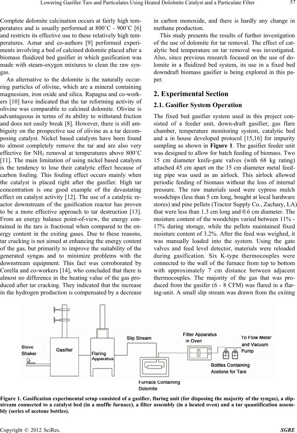 Lowering Gasifier Tars and Particulates Using Heated Dololmite Catalyst and a Particulate Filter 57 Complete dolomite calcination occurs at fairly high tem- peratures and is usually performed at 800˚C - 900˚C [6] and restricts its effective use to these relatively high tem- peratures. Aznar and co-authors [9] performed experi- ments involving a bed of calcined dolomite placed after a biomass fluidized bed gasifier in which gasification was made with steam-oxygen mixtures to clean the raw syn- gas. An alternative to the dolomite is the naturally occur- ring particles of olivine, which are a mineral containing magnesium, iron oxide and silica. Rapagna and co-work- ers [10] have indicated that the tar reforming activity of olivine was comparable to calcined dolomite. Olivine is advantageous in terms of its ability to withstand friction and does not easily break [8]. However, there is still am- biguity on the prospective use of olivine as a tar decom- posing catalyst. Nickel based catalysts have been found to almost completely remove the tar and are also very effective for NH3 removal at temperatures above 800˚C [11]. The main limitation of using nickel based catalysts is the tendency to lose their catalytic effect because of carbon fouling. This fouling effect occurs mainly when the catalyst is placed right after the gasifier. High tar concentration is one good example of the devastating effect on catalyst activity [12]. The use of a catalytic re- actor downstream of the gasification reactor has proven to be a more effective approach to tar destruction [13]. From an energy balance point-of-view, the energy con- tained in the tars is fractional when compared to the en- ergy content in the exiting gases. Due to these reasons, tar cracking is not aimed at enhancing the energy content of the gas, but primarily to improve the suitability of the generated syngas and to minimize problems with the downstream equipment. This fact was corroborated by Corella and co-workers [14], who concluded that there is almost no difference in the heating value of the gas pro- duced af ter tar cracking. They indicated that the increase in the hydrogen production is compensated by a decrease in carbon monoxide, and there is hardly any change in methane production . This study presents the results of further investigation of the use of dolomite for tar removal. The effect of cat- alytic bed temperature on tar removal was investigated. Also, since previous research focused on the use of do- lomite in a fluidized bed system, its use in a fixed bed downdraft biomass gasifier is being explored in this pa- per. 2. Experimental Section 2.1. Gasifier System Operation The fixed bed gasifier system used in this project con- sisted of a feeder unit, down-draft gasifier, gas flare chamber, temperature monitoring system, catalytic bed and a in house developed protocol [15,16] for impurity sampling as shown in Figure 1. The gasifier feeder unit was designed to allow for b atch feeding of biomass. Two 15 cm diameter knife-gate valves (with 68 kg rating) attached 45 cm apart on the 15 cm diameter metal feed- ing pipe was used as an airlock. This airlock allowed periodic feeding of biomass without the loss of internal pressure. The raw materials used were cypress mulch woodchips (less than 5 cm long, bought at local hardware stores) and pine pellets (Tractor Supply Co., Zachary, LA) that were less than 1.3 cm long and 0.6 cm diameter. The moisture con tent of the woodch ips varied between 11% - 17% during storage, while the pellets maintained fixed moisture content of 3.2%. After the feed was weighed, it was manually loaded into the system. Using the gate valves and feed level detector, materials were reloaded during gasification. Six K-type thermocouples were connected to the wall of the furnace from top to bottom with approximately 7 cm distance between adjacent thermocouples. The majority of the gas that was pro- duced from the gasifer (6 - 8 CFM) was flared in a flar- ing-unit. A small slip stream was drawn from the exiting Figure 1. Gasification experimental setup consisted of a gasifier, flaring unit (for disposing the majority of the syngas), a slip- stream connected to a catalyst bed (in a muffle furnace), a filter assembly (in a heated oven) and a tar quantification assem- ly (series of acetone bottles). b Copyright © 2012 SciRes. SGRE  Lowering Gasifier Tars and Particulates Using Heated Dololmite Catalyst and a Particulate Filter 58 syngas and was used for tar-cracking and particulate cleaning experiments as discussed below. 2.2. Maintaining the Integrity of the Specifications Evaluation of the Gas Cleaning Component A small slip-stream of 94.4 cm3/s (0.2 CFM) was used for all gas cleaning experiments. The first component of the gas cleaning assembly consisted in a dolomite bed, set inside an electrically heated muffle furnace. The temperature of the dolomite bed was varied from 650˚C to 950˚C by altering the thermostat setting of the muffle furnace. A fixed-bed reactor (2.36 mm diameter) was used for all catalyst experiments. The fixed-bed had an internal diameter of 19 mm and length of 152.4 mm made from a steel pipe and was placed inside a muffle furnace. Catalyst depth in the pipe was 101.6 mm supported by wire mesh at both ends of the pipe. Prior to the experimentation involving dolomite, calcination of the dolomite was done at 850˚C in a furnace for 2 hours. The second component of the gas cleaning assembly included a glass fiber filter (Whatman: GF/F Cat No 1825 090) and a filter holder assembly placed inside an electrically heated oven for particulates removal and quantification. The filter assembly was heated to 250˚C to prevent tar condensation on the filter paper. The particulates collected on the filter paper were quantified gravimetrically. 2.3. Sampling and Analysis The syngas sampling was initiated after steady state temperatures were reached inside the gasifier. The steady- state point was also indicated by a self-sustainable flame in the flaring unit.As indicated earlier, the bulk portion of the produced syngas (6 - 8 CFM) was flared and all the gas conditioning experiments were conducted on a small 94.4 cm3/s (0.2 CFM) slip-stream of the generated syn- gas. The sampled gas was passed through insulated 0.32 cm copper tubing to the filter assembly, where the par- ticulates were collected. The filter assembly in the oven was maintained at 250˚C, which prevented tars from condensing on the filter. The gas exiting the filter oven was passed through a series of four impinger bottles containing acetone, which collected the tars by dissolu- tion (Figure 2). Passing the gas through a series of bot- tles ensured total collection of tars and number of bottles to be used in series was decided based on the amount of tars collected in the various impinger bottles during the trial runs. Due to restrictions and depositions on the filter paper, the sample gas flow rate dr opped from 94.4 cm3/s to 78 .7 cm3/s after 30 minutes of sampling. The lowering of air flow was anticipated prior to running the experiments and appropriate adjustments were made during the quan- tification of tar and particulate concentrations. The syngas exiting the acetone bottles was drawn through a volatile organic carbon absorber and a flow regulator before entering the vacuum pump. The gas ex- iting the vacuum pump was tested for syngas composi- tion. The gas samples were drawn using a 10 ml syringe with a 0.3 µm syringe filter. The collected sample was then analyzed using a gas chromatograph (SRI, MG#1) equipped with a 0.32 cm stainless steel silica gel-pack column and a thermal conductivity detector. An amount of 1 mL of gas sample was injected into the gas chroma- tography and ultra-high purity helium at a flow rate of 10 mL/min was used a carrier gas [15,16]. 3. Results and Discussion 3.1. Gasifier Temperature Profile The temperature of the gasifier during operation was continuously measured and recorded by a PC based data acquisition system. Temperature averages were calcu- lated within a 30 seconds interval and average tempera- ture profiles were created. Figure 3 shows a typical steady-state gasification temperature profile within the gasifier at various locations from the bottom grate. Tem- perature 1 represents the thermocouple immediately above the grate, and Temperature 2 to Temperature 6 represents the temperatures from thermocouples that Figure 2. An in-house built particulate and tar quantification system was used for the present study. The particulate quantification unit consited of an stainless steel assembly placed inside an oven maintaiend at 250˚C. A series of four impinger bottles containing acetone collected the tars, and the syngas exiting the acetone bottles was drawn through a volatile organic carbon absorber and a flow regulator before entering the vacuum pump and tested for composition. Copyright © 2012 SciRes. SGRE  Lowering Gasifier Tars and Particulates Using Heated Dololmite Catalyst and a Particulate Filter 59 Figure 3. Temperature profile as gasification approaches steady state. Temperature 1 represents the thermocouple immediately above the grate, and Temperature 2 to Tem- perature 6 represents the temperatures from thermocouples that were placed approximately 7 cm higher than the pre- ceding thermocouple. were placed approximately 7 cm higher than the preced- ing thermocouple. Based on the construction of the gasifier and the inlet ports (which were place between thermocouples 3 and 4), the highest steady-state temperatures (or oxidation zone) will be experienced by Temperature 2. All temperatures measured were relatively constant. However, Tempera- ture 1 had a sharp decrease at about 35 min due to a malfunction of the grate which lead to a small accumula- tion of ash close to the thermocouple. This problem was promptly fixed resulting in a more accurate temperature profile. Based on experimental observations, true gasification, as indicated by a self-sustainable flame in the flaring unit, occurs when the Temperature 2 temperatures exceed 700˚C [17]. The high reactor temperature obtained also reduces the producti on of de tectable tar species [18]. 3.2. Gas Composition and Heating Value The average yield of measured syngas components from wood chips and pine pellets are shown in Figure 4. The average concentrations of the combustible gases namely: carbon monoxide (CO), hydrogen (H2), and methane (CH4) obtained were within the limits reported in previ- ous work [3]. However, the high percentage of nitrogen (N2) present in the gas mixture could be explained by the fact that air was used as the gasification medium. The use of pure oxygen will result in higher percentages of the combustible gases; however, no additional efforts were made to lower the nitrogen content for this study. The attempt to minimize the air flow from the blower did not seem to have any noticeable effect on the gas composi- Figure 4. Volumetric concentration of combustible gases in the syngas from wood chips and pine pellets after gasifica- tion. tion (data not shown) but rather reduced the velocity of the syngas flowing from the gasification chamber. The heating value of a gas cannot be measured directly, but only with respect to a reference state. The most widely used is th e Lower Heating Value (LHV), parameter that- defines the potential energy available per unit volume of the biomass. This uses water vapor as its reference state. The heating value of the syngas was calculated from the concentration of combustible gases in the mixture. Lower Heating Value (LHV) = %H2 × LHVH2 + %CH4 × LHVCH 4 + %CO × LHVCO The heating values obtained were within the range of previous work using woodchips as raw materials. A com- parison with data published on gasification with similar systems is presented in Table 1. 3.3. Gravimetric Tar and Particulates The process of tar and particulate sampling was initiated only after the temperatures in the gasifier approached steady state and there was evidence of combustible gases produced, indicated by a self-sustaining flame. Figure 5 Table 1. Comparison of wood chips and pine pellets syngas composition from experimental results with literature pub- lished data. Parameters Published Data [3]Experimental Results Wood Chips Experimental Results Pine Pellets H2 (% Vol.)15 - 2111.56 11.44 CO (% Vol.)10 - 2212.09 13.49 CO2 (% Vol.)11 - 1312.50 12.98 CH4 (% Vol.)1 - 5 1.70 2.05 N2 (% Vol.)39 - 6362.16 59.73 LHV(MJ/Nm3)4.0 - 5.63.38 3.67 Copyright © 2012 SciRes. SGRE 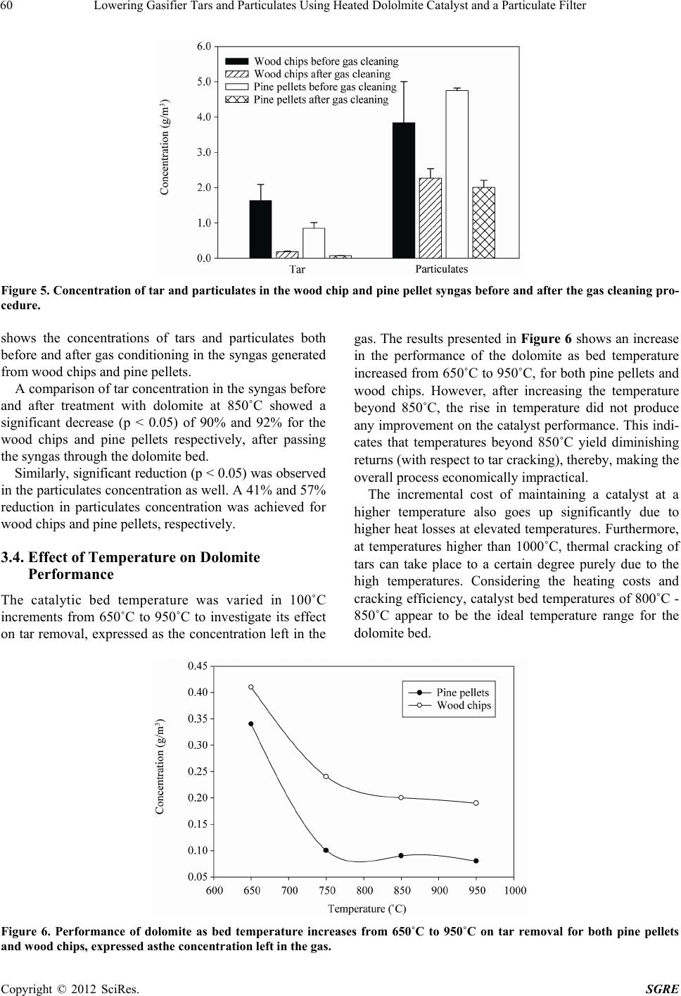 Lowering Gasifier Tars and Particulates Using Heated Dololmite Catalyst and a Particulate Filter 60 Figure 5. Concentration of tar and particulates in the wood chip and pine pellet syngas before and after the gas cle aning pro- cedure. shows the concentrations of tars and particulates both before and after gas conditio ning in the syngas generated from wood chips and pine pellets. A comparison of tar concentration in the syngas before and after treatment with dolomite at 850˚C showed a significant decrease (p < 0.05) of 90% and 92% for the wood chips and pine pellets respectively, after passing the syngas through the dolomite bed. Similarly, significant reduction (p < 0.05) was observed in the particulates concen tration as well. A 41% and 57% reduction in particulates concentration was achieved for wood chips and pine pellets, respectively. 3.4. Effect of Temperature on Dolomite Performance The catalytic bed temperature was varied in 100˚C increments from 650˚C to 950˚C to investigate its effect on tar removal, expressed as the concentration left in the gas. The results presented in Figure 6 shows an increase in the performance of the dolomite as bed temperature increased from 650˚C to 950˚C, for both pine pellets and wood chips. However, after increasing the temperature beyond 850˚C, the rise in temperature did not produce any improvement on the catalyst performance. This indi- cates that temperatures beyond 850˚C yield diminishing returns (with respect to tar cracking), th ereby, making th e overall process economically impractical. The incremental cost of maintaining a catalyst at a higher temperature also goes up significantly due to higher heat losses at elevated temperatures. Furthermore, at temperatures higher than 1000˚C, thermal cracking of tars can take place to a certain degree purely due to the high temperatures. Considering the heating costs and cracking efficiency, catalyst bed temperatures of 800˚C - 850˚C appear to be the ideal temperature range for the dolomite bed. Figure 6. Performance of dolomite as bed temperature increases from 650˚C to 950˚C on tar removal for both pine pellets nd wood chips, expressed asthe concentration left in the gas. a Copyright © 2012 SciRes. SGRE  Lowering Gasifier Tars and Particulates Using Heated Dololmite Catalyst and a Particulate Filter 61 4. Conclusion Gasification of biomass for energy production requires effective gas cleaning techniques that removes the tars and particulates formed during process. In this study, dolomite was investigated for its tar cracking capability in a downdraft gasification system. Temperature studies indicate an optimum catalytic bed performance at 800˚C - 850˚C. The gravimetric analysis presented in this p aper is an attempt to overcome the tar and particulate prob- lems associated with biomass gasification. Additional work is needed in order to investigate the tar cracking potential of proprietary low temperature catalysts and a possible combination of different catalytic bed reactors. A chemical analysis of the tar components and deposits on the spent catalyst (if any) is needed to better under- stand and design a gasification system. REFERENCES [1] J. Gil, M. P. Aznar, M. A. Caballero, E. Frances and J. Corella, “Biomass Gasification in Fluidized Bed at Pilot Scale with Steam-Oxygen Mixtures. Product Distribution for Very Different Operating Conditions,” Energy & Fu- els, Vol. 11, No. 6, 1997, pp. 1109-1118. doi:10.1021/ef9602335 [2] I. Narvaez, A. Orio, M. P. Aznar and J. Corella, “Biomass Gasification with Air in an Atmospheric Bubbling Fluid- ized Bed. Effect of Six Operational Variables on the Quality of the Produced Raw Gas,” Industrial & Engi- neering Chemistry Research, Vol. 35, No. 7, 1996, pp. 2110-2120. doi:10.1021/ie9507540 [3] A. J. M. Pemen, E. J. M. van Heesch, K. Yan, S. V. B. van Paasen, K. J. Ptasinski, Z. Matyas, P. A. Huijbrechts, B. O. E. Hultermans, A. Nicoletti, P. P. M. Blom and P. Zacharias, “Experimental Program of the Pulsed Corona Tar Cracker,” Conference Paper for Pulse Power Con- ference. Digest of Technical Papers. 12th IEEE Interna- tional, Monterey, CA, Vol. 1, 1999, pp. 515-518. [4] J. Herguido, J. Corella and J. Gonzalezsaiz, “Steam Gasi- fication of Lignocellulosic Residues in a Fluidized-Bed at a Small Pilot Scale—Effect of the Type of Feedstock,” Industrial & Engineering Chemistry Research, Vol. 31, No. 5, 1992, pp. 1274-1282. doi:10.1021/ie00005a006 [5] T. A. Milne, N. Abatzoglou and R. J. Evans, “Biomass Gasifier Tars: Their Nature, Formation, and Conversion,” NREL Report, NREL/TP-570-25357, NREL, Golden, CO, 1998. [6] D. Dayton, “A Review of the Literature on Catalytic Biomass Tar Destruction,” NREL Report, NREL/TP-510- 32815, NREL, Golden, CO, 2002. [7] J. Delgado, M. P. Aznar and J. Corella, “Calcined Do- lomite, Magnesite, and Calcite for Cleaning Hot Gas from a Fluidized Bed Biomass Gasifier with Steam: Life and Usefulness,” Industrial & Engineering Chemistry Re- search, Vol. 35, No. 10, 1996, pp. 3637-3643. doi:10.1021/ie950714w [8] L. Devi, K. J. Ptasinski, F. Janssen, S. V. B. van Paasen, P. C. A. Bergman and J. H. A. Kiel, “Catalytic Decompo- sition of Biomass Tars: Use of Dolomite and Untreated Olivine,” Renewable Energy, Vol. 30, No. 4, 2005, pp. 565-587. doi:10.1016/j.renene.2004.07.014 [9] M. P. Aznar, J. Corella, J. Gil, J. A. Martin, M. A. Cabal- lero, A. Olivares, P. Perez and E. Frances, “Biomass Ga- sification with Steam and Oxygen Mixtures at Pilot Scale and with Catalytic Gas Upgrading. Part I: Perform- ance of the Gasifier,” In: A. V. Bridgwater and D. G. B. Boo- cock, Eds., Developments in Thermochemical Bio- mass Conversion, Kluwer Academic Publishers, London, 1997, pp. 1194-1208. [10] S. Rapagna, N. Jand, A. Kiennemann and P. U. Foscolo, “Steam-Gasification of Biomass in a Fluidised-Bed of Olivine Particles,” Biomass & Bioenergy, Vol. 19, No. 3, 2000, pp. 187-197. doi:10.1016/S0961-9534(00)00031-3 [11] W. Y. Wang, N. Padban, Z. C. Ye, A. Andersson and I. Bjerle, “Kinetics of Ammonia Decomposition in Hot Gas Cleaning,” Industrial & Engineering Chemistry Research, Vol. 38, No. 11, 1999, pp. 4175-4182. doi:10.1021/ie990337d [12] S. Anis and Z. A. Zainal, “Tar Reduction in Biomass Producer Gas via Mechanical, Catalytic and Thermal Me- thods: A Review,” Renewable & Sustainable Energy Re- views, Vol. 15, No. 5, 2011, pp. 2355-2377. doi:10.1016/jsser.2011.02.018 [13] E. Kurkela, P. Stahlberg, J. Laatikainen and P. Simell, “Development of Simplified Igcc-Processes for Biofuels- Supporting Gasification Research at VTT,” Bioresource Technology, Vol. 46, No. 1-2, 1993, pp. 37-47. doi:10.1016/0960-8524(93)90052-D [14] J. Corella, M. P. Aznar, J. Gil and M. A. Caballero, “Bio- mass Gasification in Fluidized Bed: Where to Locate the Dolomite to Improve Gasification?” Energy & Fuels, Vol. 13, No. 6, 1999, pp. 1122-1127. doi:10.1021/ef990019r [15] C. O. Akudo and C. S. Theegala, “Sampling and Analysis of Tars and Particulates from a Biomass Downdraft Gasi- fier,” Conference Paper for ASABE Annual International Meeting, Minneapolis, Paper No. 074149, 17-20 June 2007, pp. 1-7. [16] C. O. Akudo, “Quantification of Tars and Particulates from a Pilot Scale, Downdraft Biomass Gasifier,” Masters Thesis, Louisiana State University, Baton Rouge, 2008. [17] L. Wei, “Experimental Study on the Effects of Opera- tional Parame ters of a Downdraft Gasifier,” Masters The- sis, Mississippi State University, Starkville, 2005. [18] C. M. Kinoshita, Y. Wang and J. Zhou, “Tar Formation under Different Biomass Gasification Conditions,” Jour- nal of Analytical and Applied Pyrolysis, Vol. 29, No. 2, 1994, pp. 169-181. doi:10.1016/0165-2370(94)00796-9 Copyright © 2012 SciRes. SGRE |