

Paper Menu >>
Journal Menu >>
 Materials Sciences and Applicatio ns, 2011, 2, 1697-1701 doi:10.4236/msa.2011.212226 Published Online December 2011 (http://www.SciRP.org/journal/msa) Copyright © 2011 SciRes. MSA 1697 The Role of Oxide Thin Layer in Inverted Structure Polymer Solar Cells Orawan Wiranwetchayan1,2, Zhiqiang Liang1, Qifeng Zhang1, Guozhon g Cao1*, Pisith Singjai2 1Department of Materials Science and Engineering, University of Washington, Seattle, USA; 2Department of Physics and Material Science, Faculty of Science, Chiang Mai University, Chiang Mai, Thailand. E-mail: *[email protected] Received September 19th, 2011; revised October 24th, 2011; accepted November 6th, 2011. ABSTRACT The role of wide band gap oxide thin layer in inverted structure polymer solar cells was investigated by employing ox- ide films of TiO2 and Nb2O5 approximately 10 nm in thickness deposited onto FTO substrates. The experimental re- sults demonstrated that the thin oxide layer serving to separate the electron collecting electrode and the photoactive film of a blend of poly(3-hexylthioph ene) (P3HT) and phenyl-C61-butyric acid methyl ester (PCBM) was necessary to promote the formation of continuous uniform PCBM film to block holes in P3HT from being recombined with electrons in collecting electrode. A use of TiO2 buffer layer leads to power conversion efficiency as high as 2.8%. As for Nb2O5, in spite the fact that its conduction band is higher than the LUMO level of PCBM polymer acting as electron transport material, a power conversion of 2.7%, which was only slightly different from the 2.8% achieved for the cell employing TiO2. These experimental results suggest a tunneling mechanism for the electrons to transport from the PCBM to col- lecting electrode over the oxide film, instead of a diffusion through the oxide film arising from either energy or concen- tration difference of the photogenerated electrons. Keywords: Polymer Solar Cell, Oxide Thin Film, TiO2 Thin Film, Nb2O5 Thin Film 1. Introduction Photovoltaic cells based on conjugated polymer and full- erene bulk heterojuction composites have attracted much attention for renewable energy due to their promising properties such as low production cost, their lightness, light weight, mechanical flexibility and the possibility of fabricating them on large area [1-5]. Recent the power conversion efficiency (PCE) of the bulk heterojunction polymer solar cells has reached as high as 7.4% in con- ventional device structures [6]. Conventional organic photovoltaics, OPVs generally consist of an active layers sandwiched by a high work function and transparent metal oxide as the anode such as PEDOT:PSS and a low function metal as the cathode such as Al [7]. In spite of high PCE, the conventional OPVs can suffer from deg- radation of the cathode due to their sensitivity to oxygen and moisture in air. Therefore, the devices in this struc- ture exhibit short lifetime [8-10]. In order to overcome these problems, the inverted device structures is an alter- ative solution to improve the durability, because it uses a more air-stable high work function electrode such (Ag, Au) as back contact to collect holes while using an inor- ganic semiconductor for buffer layer to collect electrons. The usage of inorganic semiconductor embedded into the conjugated polymer have several attributes as electron acceptors, including relatively high electron mobility, high electron affinities, hole-blocking ability and good physical and chemical stability [11-16]. In this work we report the fabrication of inverted polymer solar cells and investigate the role of thin dense metal oxide films in the inverted polymer solar cells us- ing dense film of TiO2 and Nb2O5. These two oxides were purposely selected in view of the bottom of con- duction band of TiO2 lower than the LUMO level of PCBM and that of Nb2O5 higher than the LUMO level of PCBM. It was found that such a very thin metal oxide films between the electron collecting electrode and active layers was necessary to promote the formation of con- tinuous uniform PCBM film and thus block the holes in P3HT from being recombined with the electrons in col- lecting electrode. 2. Experiment Details 2.1. Preparation of TiO2 Sol and Nb2O5 Sol TiO2 sol was prepared by hydrolyzing titanium alkoxide in an acidic aqueous. Typically, 1 mL of titanium iso- 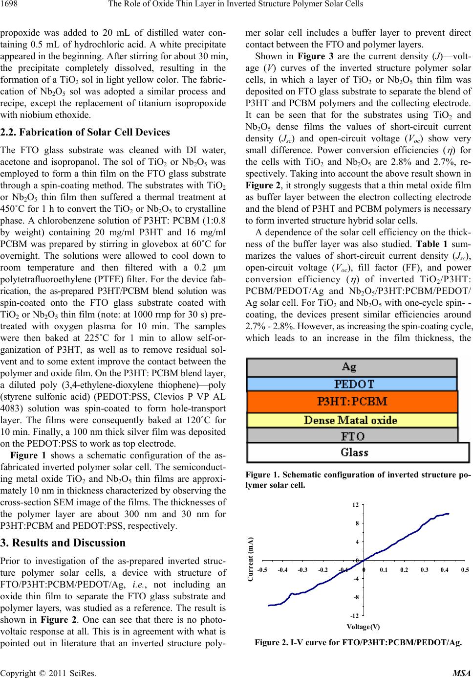 The Role of Oxide Thin Layer in Inverted Structure Polymer Solar Cells 1698 propoxide was added to 20 mL of distilled water con- taining 0.5 mL of hydrochloric acid. A white precipitate appeared in the beginning. After stirring for about 30 min, the precipitate completely dissolved, resulting in the formation of a TiO2 sol in light yellow color. The fabric- cation of Nb2O5 sol was adopted a similar process and recipe, except the replacement of titanium isopropoxide with niobium ethoxide. 2.2. Fabrication of Solar Cell Devices The FTO glass substrate was cleaned with DI water, acetone and isopropanol. The sol of TiO2 or Nb2O5 was employed to form a thin film on the FTO glass substrate through a spin-coating method. The substrates with TiO2 or Nb2O5 thin film then suffered a thermal treatment at 450˚C for 1 h to convert the TiO2 or Nb2O5 to crystalline phase. A chlorobenzene solution of P3HT: PCBM (1:0.8 by weight) containing 20 mg/ml P3HT and 16 mg/ml PCBM was prepared by stirring in glovebox at 60˚C for overnight. The solutions were allowed to cool down to room temperature and then filtered with a 0.2 μm polytetrafluoroethylene (PTFE) filter. For the device fab- rication, the as-prepared P3HT/PCBM blend solution was spin-coated onto the FTO glass substrate coated with TiO2 or Nb2O5 thin film (note: at 1000 rmp for 30 s) pre- treated with oxygen plasma for 10 min. The samples were then baked at 225˚C for 1 min to allow self-or- ganization of P3HT, as well as to remove residual sol- vent and to some extent improve the contact between the polymer and oxide film. On the P3HT: PCBM blend layer, a diluted poly (3,4-ethylene-dioxylene thiophene)—poly (styrene sulfonic acid) (PEDOT:PSS, Clevios P VP AL 4083) solution was spin-coated to form hole-transport layer. The films were consequently baked at 120˚C for 10 min. Finally, a 100 nm thick silver film was deposited on the PEDOT:PSS to work as top electrode. Figure 1 shows a schematic configuration of the as- fabricated inverted polymer solar cell. The semiconduct- ing metal oxide TiO2 and Nb2O5 thin films are approxi- mately 10 nm in thickness characterized by observing the cross-section SEM image of the films. The thicknesses of the polymer layer are about 300 nm and 30 nm for P3HT:PCBM and PEDOT:PSS, respectively. 3. Results and Discussion Prior to investigation of the as-prepared inverted struc- ture polymer solar cells, a device with structure of FTO/P3HT:PCBM/PEDOT/Ag, i.e., not including an oxide thin film to separate the FTO glass substrate and polymer layers, was studied as a reference. The result is shown in Figure 2. One can see that there is no photo- voltaic response at all. This is in agreement with what is pointed out in literature that an inverted structure poly- mer solar cell includes a buffer layer to prevent direct contact between the FTO and polymer layers. Shown in Figure 3 are the current density (J)—volt- age (V) curves of the inverted structure polymer solar cells, in which a layer of TiO2 or Nb2O5 thin film was deposited on FTO glass substrate to separate the blend of P3HT and PCBM polymers and the collecting electrode. It can be seen that for the substrates using TiO2 and Nb2O5 dense films the values of short-circuit current density (Jsc) and open-circuit voltage (Voc) show very small difference. Power conversion efficiencies ( ) for the cells with TiO2 and Nb2O5 are 2.8% and 2.7%, re- spectively. Taking into account the above result shown in Figure 2, it strongly suggests that a thin metal oxide film as buffer layer between the electron collecting electrode and the blend of P3HT and PCBM polymers is necessary to form inverted structure hybrid solar cells. A dependence of the solar cell efficiency on the thick- ness of the buffer layer was also studied. Table 1 sum- marizes the values of short-circuit current density (Jsc), open-circuit voltage (Voc), fill factor (FF), and power conversion efficiency ( ) of inverted TiO2/P3HT: PCBM/PEDOT/Ag and Nb2O5/P3HT:PCBM/PEDOT/ Ag solar cell. For TiO2 and Nb2O5 with one-cycle spin- - coating, the devices present similar efficiencies around 2.7% - 2.8%. However, as increasing the spin-coating cycle, which leads to an increase in the film thickness, the Figure 1. Schematic configuration of inverted structure po- lymer solar cell. -12 -8 -4 0 4 8 12 -0.5 -0.4-0.3 -0.2 -0.100.10.20.30.40.5 Voltage(V) Current (mA) Figure 2. I-V curve for FTO/P3HT:PCBM/PEDOT/Ag. Copyright © 2011 SciRes. MSA 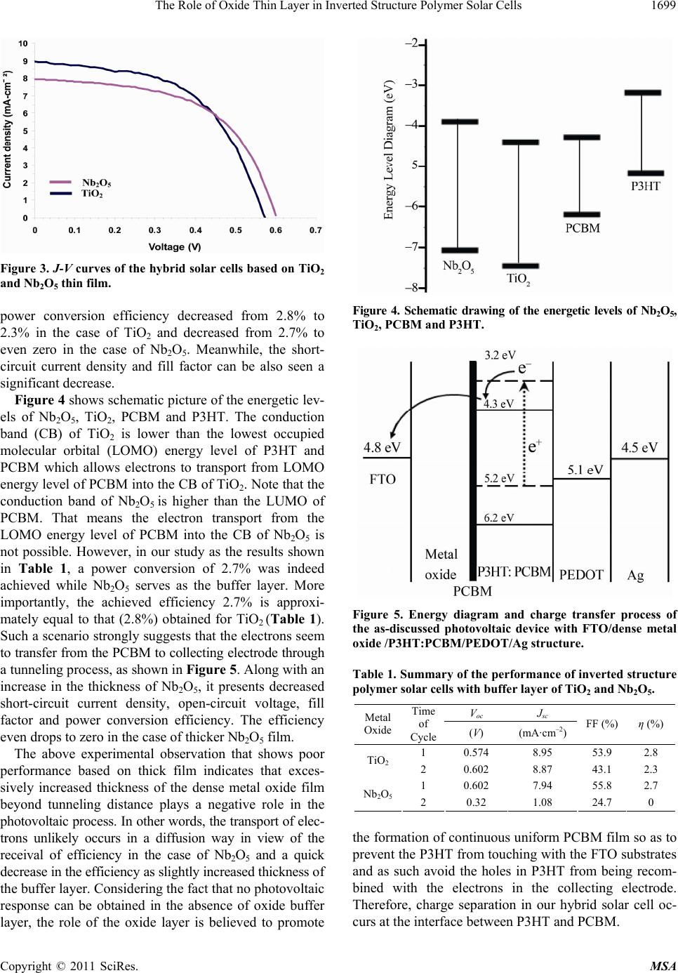 The Role of Oxide Thin Layer in Inverted Structure Polymer Solar Cells1699 Figure 3. J-V curves of the hybrid solar cells based on TiO2 and Nb2O5 thin film. power conversion efficiency decreased from 2.8% to 2.3% in the case of TiO2 and decreased from 2.7% to even zero in the case of Nb2O5. Meanwhile, the short- circuit current density and fill factor can be also seen a significant decrease. Figure 4 shows schematic picture of the energetic lev- els of Nb2O5, TiO2, PCBM and P3HT. The conduction band (CB) of TiO2 is lower than the lowest occupied molecular orbital (LOMO) energy level of P3HT and PCBM which allows electrons to transport from LOMO energy level of PCBM into the CB of TiO2. Note that the conduction band of Nb2O5 is higher than the LUMO of PCBM. That means the electron transport from the LOMO energy level of PCBM into the CB of Nb2O5 is not possible. However, in our study as the results shown in Table 1, a power conversion of 2.7% was indeed achieved while Nb2O5 serves as the buffer layer. More importantly, the achieved efficiency 2.7% is approxi- mately equal to that (2.8%) obtained for TiO2 (Table 1). Such a scenario strongly suggests that the electrons seem to transfer from the PCBM to collecting electrode through a tunneling process, as shown in Figure 5. Along with an increase in the thickness of Nb2O5, it presents decreased short-circuit current density, open-circuit voltage, fill factor and power conversion efficiency. The efficiency even drops to zero in the case of thicker Nb2O5 film. The above experimental observation that shows poor performance based on thick film indicates that exces- sively increased thickness of the dense metal oxide film beyond tunneling distance plays a negative role in the photovoltaic process. In other words, the transport of elec- trons unlikely occurs in a diffusion way in view of the receival of efficiency in the case of Nb2O5 and a quick decrease in the efficiency as slightly increased thickness of the buffer layer. Considering the fact that no photovoltaic response can be obtained in the absence of oxide buffer layer, the role of the oxide layer is believed to promote Figure 4. Schematic drawing of the energetic levels of Nb2O5, TiO2, PCBM and P3HT. Figure 5. Energy diagram and charge transfer process of the as-discussed photovoltaic device with FTO/dense metal oxide /P3HT:PCBM/PEDOT/Ag structure. Table 1. Summary of the performance of inverted structure polymer solar cells with buffer layer of TiO2 and Nb2O5. Voc J sc Metal Oxide Time of Cycle (V) (mA·cm–2) FF (%)η (%) 1 0.574 8.95 53.9 2.8 TiO2 2 0.602 8.87 43.1 2.3 1 0.602 7.94 55.8 2.7 Nb2O52 0.32 1.08 24.7 0 the formation of continuous uniform PCBM film so as to prevent the P3HT from touching with the FTO substrates and as such avoid the holes in P3HT from being recom- bined with the electrons in the collecting electrode. Therefore, charge separation in our hybrid solar cell oc- curs at the interface between P3HT and PCBM. Copyright © 2011 SciRes. MSA  The Role of Oxide Thin Layer in Inverted Structure Polymer Solar Cells 1700 4. Conclusions Our study demonstrates that a thin oxide film coating on FTO glass substrate is necessary in inverted structure polymer solar cells to protect P3HT from touching the FTO substrates and promote the formation of continuous uniform PCBM film to block holes from being recom- bined. The electrons transport from the PCBM to the collecting electrode on FTO glass substrate through a tunneling process. A thick buffer layer would not allow the occurrence of electron tunneling and therefore leads to low efficiency or even no photovoltaic response in the inverted structure solar cells. 5. Acknowledgements This work is funded by the US Department of Energy, Office of Basic Energy Sciences, Division of Materials Sciences, under Award No. DE-FG02-07ER46467 (Q.F.Z.). This work is also supported in part by the National Sci- ence Foundation (DMR 1035196), the Air Force Office of Scientific Research (AFOSR-MURI, FA9550-06-1- 0326), the University of Washington TGIF grant, the Royalty Research Fund (RRF) from the Office of Re- search at University of Washington, the Washington Re- search Foundation, and the Intel Corporation, Office of the Higher Education Commission, Ministry of Educa- tion, Thailand. Orawan Wiranwetchayan was supported by CHE Ph.D. Scholarship, and partially supported by the Graduate School, Physics and Material Department, Faculty of Science, Chiang Mai University. REFERENCES [1] J.-C. Wang, W.-T. Weng, M.-Y. Tsai, M.-K. Lee, S.-F. Horng, T.-P. Perng, C.-C. Kei, C.-C. Yuc and H.-F. Mengd, “Highly Efficient Flexible Inverted Organic Solar Cells Using Atomic Layer Deposited ZnO as Electron Selective Layer,” Journal of Materials Chemistry, Vol. 20, No. 29, 2010, pp. 862-866. doi:10.1039/b921396a [2] S. K. Hau, H.-L. Yip, H. Ma and A. K.-Y. Jen, “High Performance Ambient Processed Inverted Polymer Solar Cells through Interfacial Modification with a Fullerene Self-Assembled Monolayer,” Applied Physics Letters, Vol. 93, No. 23, 2008, pp. 233-304. doi:10.1063/1.3028094 [3] F. Zhang , X. Xu, W. Tang, J. Zhang, Z. Zhuo, J. Wang, J. Wanga, Z. Xu and Y. Wanga, “Recent Development of the Inverted Configuration Organic Solar Cells,” Solar Energy Materials and Solar Cells, Vol. 95, No. 7, 2011, pp. 2758-2761. doi:10.1016/j.solmat.2011.02.002 [4] J.-S. Huang, C.-Y. Chou, M.-Y. Liu, K.-H. Tsai, W.-H. Lin and C.-F. Lin, “Solution-Processed Vanadium Oxide as an Anode Interlayer for Inverted Polymer Solar Cells Hybridized with ZnO Nanorods,” Organic Electronics, Vol. 10, No. 3, 2009, pp. 1060-1065. doi:10.1016/j.orgel.2009.05.017 [5] W.-H. Baek, I. Seo, T.-S. Yoon, H. H. Lee, C. M. Yun and Y.-S. Kim, “Hybrid Inverted Bulk Heterojuntion So- lar Cells with Nanoimprinted TiO2 Nanopores,” Solar Energy Materials and Solar Cells, Vol. 93, No. 9, 2009, pp. 1587-1591. doi:10.1016/j.solmat.2009.04.014 [6] Y. Liang, Z. Xu, J. Xia, S.-T. Tsai, Y. Wu, G. Li, C. Ray and L. Yu, “For the Bright Future-Bulk Heterojunction Polymer Solar Cells Eith Power Conversion Efficiency of 7.4%,” Advanced Material, Vol. 22, No. 20, 2010, pp. 1-4. doi:10.1002/adma.200903528 [7] A. K. K. Kyaw, X. W. Sun, C. Y. Jiang, G. Q. Lo, D. W. Zhao and D. L. Kwong, “An Inverted Organic Solar Cell Employing a Sol-Gel Derived ZnO Electron Selective Layer and Thermal Evaporated MoO3 Hole Selective Layer,” Applied Physics Letters, Vol. 93, No. 22, 2008, Article ID: 221107. doi:10.1063/1.3039076 [8] M. Jørgensen, K. Norrman and F. C. Krebs, “Stability/ Degradation of Polymer Solar Cells,” Solar Energy Mate- rials and Solar Cells, Vol. 92, No. 7, 2008, pp. 686-714. doi:10.1016/j.solmat.2008.01.005 [9] K. Kawano, R. Pacios, D. Poplavskyy, J. Nelson, D. D. C. Bradley and J. R. Durrant, “Degrasation of Organic Solar Cells Due to Air Exposure,” Solar Energy Materials and Solar Cells, Vol. 90, No. 20, 2006, pp. 3520-3530. doi:10.1016/j.solmat.2006.06.041 [10] F. C. Krebs, J. E. Carle, N. Cruys-Bagger, M. Andersen, M. R. Lilliedal, M. A. Hammond and S. Hvidt, “Life- times of Organic Photovoltaics: Photochemistry, Atmos- phere Effects and Barrier Layers in ITO-MEHPPV,” So- lar Energy Materials and Solar Cells, Vol. 86, No. 4, 2005, pp. 499-516. doi:10.1016/j.solmat.2004.09.002 [11] J. Boucle, P. Ravirajanac and J. Nelson, “Hybrid Poly- mermetal Oxide Thin Films for Photovoltaic Applica- tions,” Journal of Materials Chemistry, Vol. 17, No. 30, 2007, pp. 3141-3153. doi:10.1039/b706547g [12] S. Yodyingyong, X. Zhou, Q. Zhang, D. Triampo, B. Limketkai and G. Z. Cao, “Enhanced Photovoltaic Per- formance of Nanostructured Hybrid Solar Cell Using Highly Oriented TiO2 Nanorods,” Journal of Physics Chemistry, Vol. 114, 2010, pp. 21851-21855. [13] R. Zhu, C. Y. Jiang, B. Liu and S. Ramakrishna, “Hyghly Efficient Nanoporous TiO2-Polythiophene Hybrid Solar Cells Based on Interfacial Modification Using a Metal- Free Organic Dye,” Advanced Materials, Vol. 21, No. 9, 2009, pp. 994-1000. doi:10.1002/adma.200802388 [14] J.-S. Huang, C.-Y. Chou and W.-H. Lin, “Enhancing Per- formance of Organic-Inorganic Hybrid Solar Cells Using a Fullerene Interlayer from All-Solution Processing,” So- lar Energy Materials and Solar Cells, Vol. 94, No. 10, 2010, pp. 182-186. doi:10.1016/j.solmat.2009.08.019 [15] M. N. Shan, S. S. Wang, Z. Q. Bian, J. P. Liu and Y. L. Zhao, “Hybrid Inverted Organic Photovoltaic Cells Based on Nanoporous TiO2 Films and Organic Small Mole- cules,” Solar Energy Materials and Solar Cells, Vol. 93, No. 9, 2009, pp. 1613-1617. doi:10.1016/j.solmat.2009.04.017 [16] T. Yang, W. Cai, D. Qin, E. Wang, L. Lan, X. Gong, J. Copyright © 2011 SciRes. MSA  The Role of Oxide Thin Layer in Inverted Structure Polymer Solar Cells Copyright © 2011 SciRes. MSA 1701 Peng and Y. Cao, “Solution-Processed Zinc Oxide Thin Film as a Buffer Layer for Polymer Solar Cells with an Inverted Device Structure,” Journal of Physics Chemistry, Vol. C114, 2010, pp. 6849-6853. |