

Paper Menu >>
Journal Menu >>
 J. Biomedical Science and Engineering, 2010, 3, 181-186 doi:10.4236/jbise.2010.32023 Published Online February 2010 (http://www.SciRP.org/journal/jbise/ JBiSE ). Published Online February 2010 in SciRes. http://www.scirp.org/journal/jbise Imaging characteristics of metallic interbody spacers: in vitro score evaluation of susceptibility artifacts considering different MRI sequences T. Ernstberger1,2, G. Heidrich3, G. Buchhorn4 1Clinic for Spinal Surgery, Klinikum Bad Bramstedt, Bad Bramstedt, Germany; 2Department of Orthopedic Surgery, University of Goettingen, Goettingen, Germany; 3Department of Diagnostic Radiology, University of Goettingen, Goettingen, Germany; 4Biomaterials Laboratory/Department of Orthopedic Surgery, University of Goettingenm, Goettingen, Germany. Email: [email protected], [email protected] Received 2 December 2009; revised 10 December 2009; accepted 14 December 2009. ABSTRACT Aim: Intervertebral spacers for anterior spine fusion are made of different materials, such as titanium, carbon or cobalt-chrome, which can affect the post- fusion MRI scans. Implant-related susceptibility ar- tifacts can decrease the quality of MRI scans, thwar- ting proper evaluation. This cadaver study aimed to demonstrate the extent that implant-related MRI artifacting affects the post-fusion evaluation of in- tervertebral spacers. Methods: In a cadaveric por- cine spine, we evaluated the post-implantation MRI scans of 2 metallic intervertebral spacers (TiAL6V4, CoCrMo) that differed in shape, material, surface qualities and implantation technique. A spacer made of human cortical bone was used as a control. The median sagittal MRI slice was divided into 12 regions of interest (ROI). Results: No significant differences were found on 15 different MRI sequences read in- dependently by an interobserver-validated team of specialists (P>0.05). Artifact-affected image quality was rated on a score of 0-1-2. A maximum score of 24 points (100%) was possible. Turbo spin echo sequences produced the best scores for all spacers and the con- trol. Only the control achieved a score of 100%. The titanium and cobalt-chrome spacers scored 62.5% and 50%, respectively. Conclusions: Our scoring system allowed us to create an implant-related rank- ing of MRI scan quality in reference to the control that was independent of artifact dimensions. Even with turbo spin echo sequences, the susceptibility artifacts produced by the metallic spacers showed a high degree of variability. Despite optimum sequen- cing, implant design and material are relevant fac- tors in MRI artifacting. Keywords: Intervertebral Spacers; Metallic Implant Materials; MRI; Susceptibility Artifacts 1. INTRODUCTION In the preoperative diagnostics of spinal diseases, mag- netic resonance imaging (MRI) is used as a standard procedure that can visualize disc pathologies and neuro- logical changes of the spinal canal with high precision. When anterior spine fusion proves indicated, implanta- tion of intervertebral spacers often represents the treat- ment of choice. The selection of implant design, implant material and implantation technique is dictated by the diagnostic findings. Intervertebral spacers made of vari- ous materials can be used as stand-alone cages for ex- clusively anterior fusion or in combination with dorsal instrumentation for dorsoventral fusion. When postoperative complications arise secondary to vertebra fusion, MRI scans are frequently necessary to evaluate implant position and demonstrate any clinically relevant abnormalities and to direct further surgical deci- sion-making [1]. Depending on the material, however, implant-related susceptibility artifacts can decrease the quality of MRI scans, thereby thwarting proper evaluation. Depending on the problem to be clarified, consideration must be given to whether the MRI sequence selected will ensure the most artifact-free visualization and enable proper evaluation of implant positioning and/or patho- logical processes like tumorous growth or infection. Recent studies have shown that artifacting, particularly caused by metallic implants, can also be minimized through modification of routine MRI sequences [2,3,4]. This cadaveric porcine study was conducted to determine the extent to which implant-related MRI artifacting affects the evaluation of intervertebral spacers. A scoring system (0-1-2) was developed to rank the artifacting produced by different intervertebral spacer designs compared with a human cortical bone control. Scans taken with 15 different MRI sequences were read independently by an inter- observer-validated team of specialists who ranked image 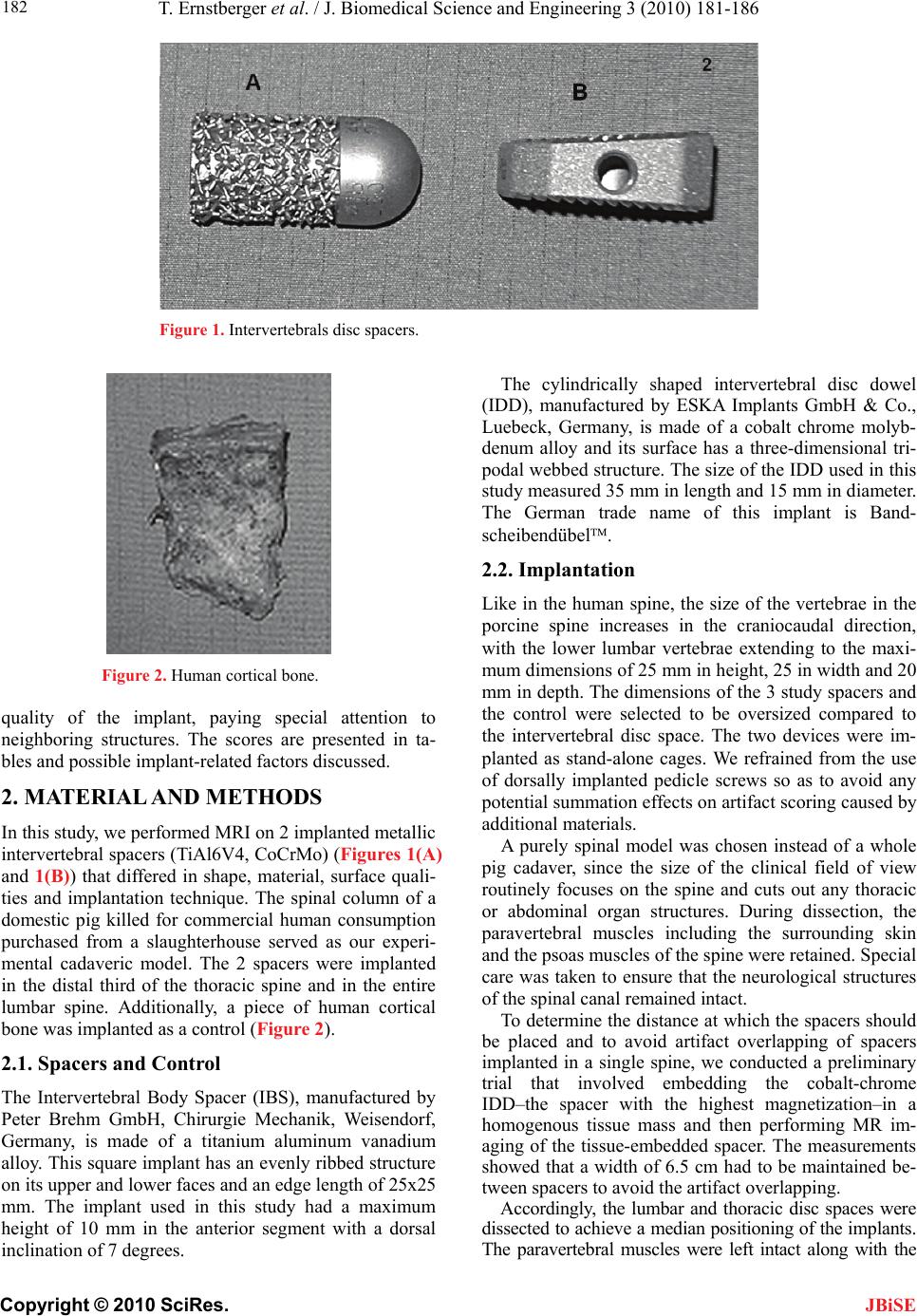 T. Ernstberger et al. / J. Biomedical Science and Engineering 3 (2010) 181-186 Copyright © 2010 SciRes. 182 JBiSE Figure 1. Intervertebrals disc spacers. Figure 2. Human cortical bone. quality of the implant, paying special attention to neighboring structures. The scores are presented in ta- bles and possible implant-related factors discussed. 2. MATERIAL AND METHODS In this study, we performed MRI on 2 implanted metallic intervertebral spacers (TiAl6V4, CoCrMo) (Figures 1(A) and 1(B)) that differed in shape, material, surface quali- ties and implantation technique. The spinal column of a domestic pig killed for commercial human consumption purchased from a slaughterhouse served as our experi- mental cadaveric model. The 2 spacers were implanted in the distal third of the thoracic spine and in the entire lumbar spine. Additionally, a piece of human cortical bone was implanted as a control (Figure 2). 2.1. Spacers and Control The Intervertebral Body Spacer (IBS), manufactured by Peter Brehm GmbH, Chirurgie Mechanik, Weisendorf, Germany, is made of a titanium aluminum vanadium alloy. This square implant has an evenly ribbed structure on its upper and lower faces and an edge length of 25x25 mm. The implant used in this study had a maximum height of 10 mm in the anterior segment with a dorsal inclination of 7 degrees. The cylindrically shaped intervertebral disc dowel (IDD), manufactured by ESKA Implants GmbH & Co., Luebeck, Germany, is made of a cobalt chrome molyb- denum alloy and its surface has a three-dimensional tri- podal webbed structure. The size of the IDD used in this study measured 35 mm in length and 15 mm in diameter. The German trade name of this implant is Band- scheibendübel. 2.2. Implantation Like in the human spine, the size of the vertebrae in the porcine spine increases in the craniocaudal direction, with the lower lumbar vertebrae extending to the maxi- mum dimensions of 25 mm in height, 25 in width and 20 mm in depth. The dimensions of the 3 study spacers and the control were selected to be oversized compared to the intervertebral disc space. The two devices were im- planted as stand-alone cages. We refrained from the use of dorsally implanted pedicle screws so as to avoid any potential summation effects on artifact scoring caused by additional materials. A purely spinal model was chosen instead of a whole pig cadaver, since the size of the clinical field of view routinely focuses on the spine and cuts out any thoracic or abdominal organ structures. During dissection, the paravertebral muscles including the surrounding skin and the psoas muscles of the spine were retained. Special care was taken to ensure that the neurological structures of the spinal canal remained intact. To determine the distance at which the spacers should be placed and to avoid artifact overlapping of spacers implanted in a single spine, we conducted a preliminary trial that involved embedding the cobalt-chrome IDD–the spacer with the highest magnetization–in a homogenous tissue mass and then performing MR im- aging of the tissue-embedded spacer. The measurements showed that a width of 6.5 cm had to be maintained be- tween spacers to avoid the artifact overlapping. Accordingly, the lumbar and thoracic disc spaces were dissected to achieve a median positioning of the implants. The paravertebral muscles were left intact along with the  T. Ernstberger et al. / J. Biomedical Science and Engineering 3 (2010) 181-186 Copyright © 2010 SciRes. 183 JBiSE skin and psoas muscles. Intervertebral discectomy was performed, and the three spacers and the control were im- planted intervertebrally apart at a distance of 6.5 cm. Maxi- mum implantation depth was reached when the implant was aligned with the anterior vertebra face. After implanta- tion was completed, additional tissue mass was padded around the spine to optimize contrast and image quality. 3. MAGNETIC RESONANCE IMAGING MRI was performed with a 1.5T MRI (Magnetom Sym- phony, Siemens AG Medical Solutions, Erlangen, Ger- many). Table 1 presents the MRI data. The median sag- ittal MRI slice encompassing all relevant structures, im- plants and control was evaluated according to an interob- server-validated scoring system. 3.1. Scoring System A 0-1-2 scoring system was established to rank the MRI scans. An evaluation unit was defined as 2 adjacent ver- tebrae encompassing the intervertebral disc space. 12 regions of interest (ROI) were demarcated (Figure 3). Every ROI could achieve a maximum score of 2 points. A total score of 24 points was equivalent to a score of 100%. Two board-certified specialists (one radiologist (GH) and one spinal surgeon (TE)) experienced in read- ing spinal MRI evaluated the scans independently of each other. The evaluators scored regions as 0=not dis- tinguishable, 1=partly distinguishable and 2=completely distinguishable. The interobserver validation of the scor- ing system across all 15 sequences was tested for statis- tical significance using a t test with a significance level of P>0.05 (Table 2). 4. RESULTS Table 3 presents the total points scored for each implant in each of the 15 sequences. Figures 4 I, II, III and IV depict the artifact range in a selection of 4 MRI sequences. Table 1. MRI sequence data. Sequences FA TR TE ST BW FOV Number of slices Matrix T1 FLASH 2D 70 181 4.8 5.5 260 500 19 256 x 256 T1 FLASH 2D FS 70 275 4.76 5.5 260 500 19 256 x 256 T2 MEDIC 2D FS 40 2660 27 3.0 70 500 40 256 x 256 T1 FLASH 3D 60 60 11 3.0 70 500 40 256 x 256 T2 DESS 3D 25 23.68 6.63 1.5 130 500 64 256 x 256 TOF FISP 3D 25 36 4.59 3.0 130 500 32 384 x 384 T2 CISS 3D 70 10.16 5.08 3.0 130 500 64 256 x 256 T1 TSE 150 2260 14 3.0 150 500 40 512 x 512 T1 TSE var 150 600 14 3.0 150 500 40 512 x 512 T1 SE 90 1270 14 3.0 90 500 40 512 x 512 T1 SE var 90 600 14 3.0 90 500 40 512 x 512 T1 SE FS var 90 684 14 3.0 90 500 40 512 x 512 T2 TSE/PD 150 6110 14 3.0 130 500 40 256 x 256 T2 TSE/PD FS 150 6760 14 3.0 130 500 40 256 x 256 STIR 180 10000 38 3.0 130 500 40 256 x 256 Key: FLASH=Fast Low Angle Shot, MEDIC=Multi Echo Data Image Combination, DESS=Dual Echo Steady State, FS=Fat Saturated, FISP=Fast Imaging with Steady Precession, CISS=Constructive Interference in Steady State, SE=Spin Echo, TSE=Turbo Spin Echo, PD=Proton density, STIR=Short Tau Inversion Recovery, TOF=Time of Flight, TR=Time of Repetition, TE=Time of Echo, FA=Flip Angle, ST=Slab Thickness, BW=Band Width, FOV=Field of View, var=varied. Interobserver validation across all 15 sequences. Figure 3. MRI Mean score value Standard deviation Spinal surgeon Radiologist Spinal surgeon Radiologist P value IBS 12.87 12.8 +1.25 +1.32 P = 0.58 IDD 8.33 8.33 +3.02 +2.85 P = 1.0 Control 20.13 20.4 +2.67 +2.79 P = 0.1 Table 2. evaluation unit with ROI.  T. Ernstberger et al. / J. Biomedical Science and Engineering 3 (2010) 181-186 Copyright © 2010 SciRes. 184 JBiSE Table 3. Total scores. MRI Sequence IBS IDD Control 1 2 1 2 1 2 T1 FLASH 2D TR:181 TE:4 13 13 9 8 18 18 T1 FLASH 2D FS TR:275 TE:4 13 13 10 10 19 19 T2 MEDIC 2D FS TR:2660 TE:27 11 11 4 4 18 18 T1 FLASH 3D FS TR:60 TE:11 10 10 5 6 15 15 T2 DESS 3D TR:23 TE:6 13 12 6 6 21 21 T2 CISS 3D TR:10 TE:5 13 12 7 7 22 23 T1 SE TR:1270 TE:14 13 14 12 12 22 23 T1 TSE TR:2260 TE:14 15 15 12 12 24 24 T1 TSE TR:600 TE:14 15 15 12 12 24 24 T1 SE TR:600 TE:14 13 13 12 12 23 23 T1 SE FS TR:684 TE:14 13 13 8 7 22 23 PD+ T2 TSE TR:6110 TE:14 13 13 8 8 19 20 PD+ T2 TSE FS TR:6760 TE:14 13 13 7 7 17 18 STIR TR:10000 TE:38 13 13 10 10 19 19 TOF FISP 3D TR:36 TE:4 12 12 3 4 19 18 Key: 1) spinal surgeon; 2) radiologist. Figure 4. I-IV: Artifact range of the different MRI sequences [I: T1 TSE (TR: 2260, TE: 14); II: T2 DESS 3D (TR: 23, TE: 6); III: T1 FLASH 2D (TR: 181, TE: 4); IV: TOF FISP 3D (TR: 36, TE: 4)]. The results showed that the T1-TSE sequences produced the best imaging scores for all implants. In these se- quences, the human cortical bone control achieved the maximum possible score of 100%, i.e. was completely distinguishable (Figure 5, Table 3). Therefore, we used these two sequences as a basis for following comparison 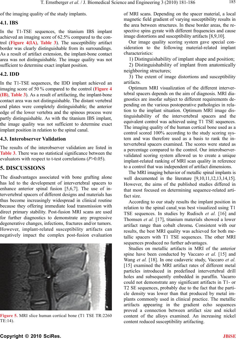 T. Ernstberger et al. / J. Biomedical Science and Engineering 3 (2010) 181-186 Copyright © 2010 SciRes. 185 JBiSE of the imaging quality of the study implants. 4.1. IBS In the T1-TSE sequences, the titanium IBS implant achieved an imaging score of 62.5% compared to the con- trol (Figure 4(IA), Table 3). The susceptibility artifact border was clearly distinguishable from its surroundings. As a result of artifact extension, the implant-bone contact area was not distinguishable. The image quality was not sufficient to determine exact implant position. 4.2. IDD In the T1-TSE sequences, the IDD implant achieved an imaging score of 50 % compared to the control (Figure 4 (IB), Table 3). As a result of artifacting, the implant-bone contact area was not distinguishable. The distant vertebral end plates were completely distinguishable; the anterior edge of the lower vertebra and the spinous process were partly distinguishable. As with the titanium IBS implant, the image quality was not sufficient to determine exact implant position in relation to the spinal canal. 4.3. Interobserver Validation The results of the interobserver validation are listed in Table 3. There was no statistical significance between the evaluators with respect to t-test correlations (P>0.05). 5. DISCUSSIONS The disadvantages associated with bone grafting alone has led to the development of intervertebral spacers to enhance anterior spinal fusion [5,6,7]. The use of in- tervertebral spacers of different designs and materials has thus become increasingly widespread in clinical routine because they offering immediate load transmission with direct primary stability. Post-fusion MRI scans are used for further diagnostics to demonstrate any progressive degenerative changes, infections, fractures and/or tumors. However, implant-related susceptibility artifacts can negatively impact the complex post-fusion evaluation Figure 5. MRI slice human cortical bone (T1 TSE TR:2260 TE:14). field gradient of varying susceptibility results in ch ne gn of MRI scans. Depending on the spacer material, a local magnetic the area between structures. In these border areas, the re- spective spins gyrate with different frequencies and cause image distortions and susceptibility artifacts [8,9,10]. Our image quality scoring system gave special con- sideration to the following material-related implant aracteristics: 1) Distinguishability of implant shape and position; 2) Distinguishability of implant from anatomically ighboring structures; 3) The extent of image distortions and susceptibility artifacts. Optimum MRI visualization of the different interver- tebral spacers depends on the aim of diagnosis. MRI dia- ostics are insofar subject to different requirements de- pending on the various postoperative pathologies in rela- tion to the implant situation. Optimum MRI image dis- tinguishability of the intervertebral spacers and the equivalent control was achieved using T1 TSE sequences. The imaging quality of the human cortical bone used as a control scored 100% according to the study scoring sys- tem and was therefore used as a basis to rank the in- tervertebral spacers examined. The scores were stated as a percentage compared to the control. Our interobserver- validated scoring system allowed us to create a unique implant-related ranking of MRI scan quality in reference to a control that was independent of artifact dimensions. The MRI imaging behavior of metallic spinal implants is well documented in the literature [9,10,11,12,13,14,15]. However, the aims of the published studies differed in that most focused on determining sequence-related arti- fact size. According to our study results the implant position in relation to the spinal canal was best visualized using T1 TSE sequences. In studies by Rudisch et al. [16] and Thomsen et al. [17], titanium materials showed a lower artifact range than cobalt chrome. Consistent with our results, the best MRI quality was achieved for both me- tallic spacers with T1 TSE sequences. The other MRI sequences produced no further advantages. Studies on metallic artifacts in MRI of the anterior spine have been conducted by Vaccaro et al. [15] and Wang et al. [18]. In one cadaveric study, Vaccaro et al. [15] examined the MRI artifact rates of different metal particles introduced in predefined intervertebral drill holes and subsequently embedded in paraffin. Vacarro could not demonstrate any significant artifacts in T1- or T2 SE sequences, probably due to the fact that the parti- cle density was lower than that produced by metal im- plants commonly used in clinical practice. The metallic artifacts appearing in the gradient echo sequences proved a connection between artifact size and nickel content of the alloys examined. An increasing nickel content reduced susceptibility artifacting. 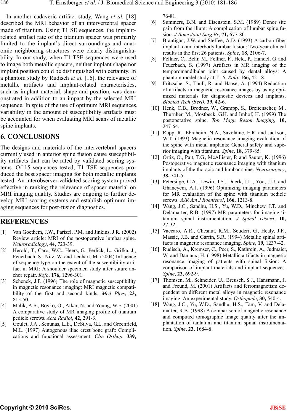 T. Ernstberger et al. / J. Biomedical Science and Engineering 3 (2010) 181-186 Copyright © 2010 SciRes. 186 tebral spacer m s of the intervertebral spacers spine fusion cause susceptibil- ., Parizel, P.M. and Jinkins, J.R. (2002) RI of the postoperative lumbar s rative study of MR imaging profile of titanium rs, B.N. and Eisenstein, S.M. (1989) Donor site ) A carbon fiber . and eduction mpp, S., Breitenseher, M., , Ebraheim, N.A., Savolaine, E.R. and Jackson, , Lewin, J.S., Duerk, J.L., Yoo, J.U. and hew, J.T. and , A.R., Chesnut, R.M., Scuderi, G., Healy, J.F., neider, U., Breusch, S.J., Hansmann, J. In another cadaveric artifact study, Wang et al. [18] described the MRI behavior of an interver JBiSE ade of titanium. Using T1 SE sequences, the implant- related artifact rate of the titanium spacer was primarily limited to the implant’s direct surroundings and anat- omic neighboring structures were clearly distinguisha- bility. In our study, when T1 TSE sequences were used to image both metallic spacers, neither implant shape nor implant position could be distinguished with certainty. In a phantom study by Rudisch et al. [16], the relevance of metallic artifacts and implant-related characteristics, such as implant material, shape and position, was dem- onstrated in addition to an impact by the selected MRI sequence. In spite of the use of optimum MRI sequences, variability in the amount of susceptibility artifacts must be accounted for when evaluating MRI scans of metallic spine implants. 6. CONCLUSIONS of a The designs and material currently used in anterior ity artifacts that can be rated by validated scoring sys- tems. Of 15 sequences tested, T1 TSE sequences pro- duced the best spacer imaging for both metallic implants tested. An interobserver-validated scoring system proved effective in ranking the relevance of spacer material on MRI imaging quality. Studies are ongoing to further de- velop MRI scoring systems and establish optimum im- aging sequences for post-fusion diagnostics. REFERENCES [1] Van Goethem, J.W Review article: Mpine. Massie, J.B. and Garfin, S.R. (1994) Metallic spinal arti- facts in magnetic resonance imaging. Spine, 19, 1237-42. [16] Rudisch, A., Kremser, C., Peer, S., Kathrein, A., Judmaier, Neuroradiology, 44, 723-39. [2] Herold, T., Caro, W.C., Heers, G., Perlick, L., Grifka, J., Feuerbach, S., Nitz, W. and Lenhart, M. (2004) Influence of sequence type on the extent of the susceptibility arti- fact in MRI: A shoulder specimen study after suture an- chor repair. Rofo, 176, 1296-301. [3] Schenck, J.F. (1996) The role of magnetic susceptibility in magnetic resonance imaging: MRI magnetic compati- bility of the first and second kinds. Med Phys, 23, 815-50. [4] Malik, A.S., Boyko, O., Atkar, N. and Young, W.F. (2001) A compa mart pedicle screws. Acta Radiol, 42, 291-3. [5] Goulet, J.A., Senunas, L.E., DeSilva, G.L. and Greenfield, M.L. (1997) Autogenous iliac crest bone graft: Compli- cations and functional assessment. Clin Orthop, 339, 76-81. [6] Summe pain from the ilium: A complication of lumbar spine fu- sion. J Bone Joint Surg Br, 71, 677-80. [7] Brantigan, J.W. and Steffee, A.D. (1993 implant to aid interbody lumbar fusion: Two-year clinical results in the first 26 patients. Spine, 18, 2106-7. [8] Fellner, C., Behr, M., Fellner, F., Held, P., Handel, G Feuerbach, S. (1997) Artifacts in MR imaging of the temporomandibular joint caused by dental alloys: A phantom model study at T1.5. Rofo, 166, 421-8. [9] Fritzsche, S., Thull, R. and Haase, A. (1994) R rtifacts in magnetic resonance images by using opti- mized materials for diagnostic devices and implants. Biomed Tech (Berl), 39, 42-6. [10] Henk, C.B., Brodner, W., Gra Thurnher, M., Mostbeck, G.H. and Imhof, H. (1999) The postoperative spine. Top Magn Reson Imaging, 10, 247-64. [11] Rupp, R. W.T. (1993) Magnetic resonance imaging evaluation of the spine with metal implants: General safety and supe- rior imaging with titanium. Spine, 18, 379-85. [12] Ortiz, O., Pait, T.G., McAllister, P. and Sauter, K. (1996) Postoperative magnetic resonance imaging with titanium implants of the thoracic and lumbar spine. Neurosurgery, 38, 741-5. [13] Petersilge, C.A. Ghaneyem, A.J. (1996) Optimizing imaging parameters for MR evaluation of the spine with titanium pedicle screws. AJR Am J Roentenol, 166, 1213-8. [14] Wang, J.C., Sandhu, H.S., Yu, W.D., Minc Delamarter, R.B. (1997) MR parameters for imaging ti- tanium spinal instrumentation. J Spinal Disord, 10, 27-32. [15] Vaccaro W. and Daniaux, H. (1998) Metallic artifacts in magnetic resonance imaging of patients with spinal fusion: A comparison of implant materials and implant sequences. Spine, 23, 692-9. [17] Thomsen, M., Sch and Freund, M. (2001) Artifacts and ferromagnetism de- pendent on different metal alloys in magnetic resonance imaging: An experimental study. Orthopade, 30, 540-4. [18] Wang, J.C., Yu, W.D., Sandhu, H.S., Tam, V. and Dela- er, R.B. (1998) A comparison of magnetic resonance and computed tomographic image quality after the im- plantation of tantalum and titanium spinal instrumenta- tion. Spine, 23, 1684-8. |