

Paper Menu >>
Journal Menu >>
 Engineering, 2010, 2, **-** doi:10.4236/eng.2010.21003 Published Online January 2010 (http://www.scirp.org/journal/eng/). Copyright © 2010 SciRes. ENGINEERING Computer Aided Modeling and Deign of a New Magnetic Sealing Mechanism in Engineering Applications Jeremy (Zheng) LI School of Engineering, University of Bridgeport, Bridgeport, USA E-mail: [email protected] Received June 6, 2009; revised August 3, 2009; accepted August 10, 2009 Abstract This article introduces a new type of magnetic sealing mechanism that reduces the lubrication oil pollution and media gaseous leakage in general reciprocating machinery including air compressors and refrigerators. The feasible function and reliable performance of this new sealing mechanism are introduced and analyzed in this paper. The computer aided design, modeling and analysis are being used to study this new sealing mechanism, and the prototype of this sealing mechanism is being tested. The study indicated the proper function of this sealing mechanism. The major advantages of this sealing mechanism include: improved sealing capacity to prevent the gaseous leakage and oil leakage, simple and compact in structure, lower pre- cision requirement on surfaces of reciprocating pistons and shafts in production and manufacturing, and longer services in sealing life span. Also there is almost no frictional loss during the reciprocating motion of piston or shaft. Keywords: Magnetic Sealing, Magnetic Flux, Reciprocating Machinery, Self-Lubricated System 1. Introduction The gaseous leakage and oil pollution in reciprocating machines including compressors and refrigerators are common problems that have not been well resolved and it directly affects the machinery performance [1–4]. The design and development of new sealing mechanism are continued in these years [5–8]. In this research, a new magnetic sealing mechanism using rare-earth magnet as permanent magnet is devel- oped to solve these problems based on theoretic analysis, computational modeling simulation, and prototype tests. The permanent magnet is made from the materials that stay magnetized. Materials that can be magnetized are called ferromagnetic including rare earth magnets. The current research and development of rare earth perma- nent magnets have brought the renovation in the field of magnetic separation and provided the magnetic products that are an order of magnitude stronger than that of con- ventional ferrite magnets. This leads to the development of high-intensity magnetic circuits that operated energy free and surpasses the electromagnets in strength and effectiveness. Common applications of rare-earth mag- nets include: computer hard drives, audio speakers, bicy- cle dynamos, fishing reel brakes, mag-lev wind turbines, and LED throwies. The prototype testing of this new magnetic sealing mechanism indicated that this sealing mechanism can significantly reduce the leakage problem in reciprocating machines including compressors and oil pollution in cryogenic regenerator. It also shows that this sealing mechanism can replace the oil separation system in re- frigerating compressors. Through the prototype tests, the sealing function of this new mechanism is better than regular rubber seal, diaphragm seal, corrugated pipe seal and magnetic fluid seal. 2. Magnetic Circuit in Sealing Mechanism The rare-earth magnet steel can be performed as a per- manent magnet steel which has the higher density of magnetic flux Br, strong magnetic field Hg, and larger product of magnetism and energy (BH)max as shown in Figure 1. All these good features allow the magnetic par- ticles to be firmly adhered onto the inside wall of magnet steel. The major advantages of this magnetic circuit in- clude higher Br in working gap of the circuit, longer and durable in sealing lifetime, compact in system configura- tion, light in unit weight, higher in performance efficien- 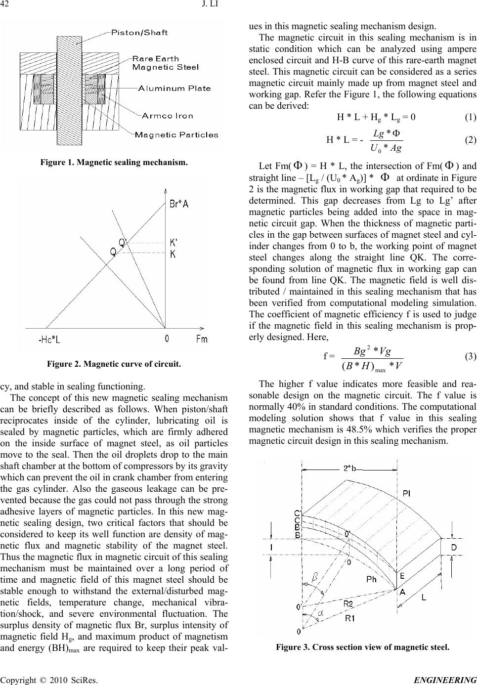 42 J. LI Figure 1. Magnetic sealing mechanism. Figure 2. Magnetic curve of circuit. cy, and stable in sealing functioning. The concept of this new magnetic sealing mechanism can be briefly described as follows. When piston/shaft reciprocates inside of the cylinder, lubricating oil is sealed by magnetic particles, which are firmly adhered on the inside surface of magnet steel, as oil particles move to the seal. Then the oil droplets drop to the main shaft chamber at the bottom of compressors by its gravity which can prevent the oil in crank chamber from entering the gas cylinder. Also the gaseous leakage can be pre- vented because the gas could not pass through the strong adhesive layers of magnetic particles. In this new mag- netic sealing design, two critical factors that should be considered to keep its well function are density of mag- netic flux and magnetic stability of the magnet steel. Thus the magnetic flux in magnetic circuit of this sealing mechanism must be maintained over a long period of time and magnetic field of this magnet steel should be stable enough to withstand the external/disturbed mag- netic fields, temperature change, mechanical vibra- tion/shock, and severe environmental fluctuation. The surplus density of magnetic flux Br, surplus intensity of magnetic field Hg, and maximum product of magnetism and energy (BH)max are required to keep their peak val- ues in this magnetic sealing mechanism design. The magnetic circuit in this sealing mechanism is in static condition which can be analyzed using ampere enclosed circuit and H-B curve of this rare-earth magnet steel. This magnetic circuit can be considered as a series magnetic circuit mainly made up from magnet steel and working gap. Refer the Figure 1, the following equations can be derived: H * L + Hg * Lg = 0 (1) H * L = - AgU Lg * * 0 (2) Let Fm( ) = H * L, the intersection of Fm( ) and straight line – [Lg / (U0 * Ag)] * at ordinate in Figure 2 is the magnetic flux in working gap that required to be determined. This gap decreases from Lg to Lg’ after magnetic particles being added into the space in mag- netic circuit gap. When the thickness of magnetic parti- cles in the gap between surfaces of magnet steel and cyl- inder changes from 0 to b, the working point of magnet steel changes along the straight line QK. The corre- sponding solution of magnetic flux in working gap can be found from line QK. The magnetic field is well dis- tributed / maintained in this sealing mechanism that has been verified from computational modeling simulation. The coefficient of magnetic efficiency f is used to judge if the magnetic field in this sealing mechanism is prop- erly designed. Here, f = VHB VgBg *)*( * max 2 (3) The higher f value indicates more feasible and rea- sonable design on the magnetic circuit. The f value is normally 40% in standard conditions. The computational modeling solution shows that f value in this sealing magnetic mechanism is 48.5% which verifies the proper magnetic circuit design in this sealing mechanism. Figure 3. Cross section view of magnetic steel. Copyright © 2010 SciRes. ENGINEERING 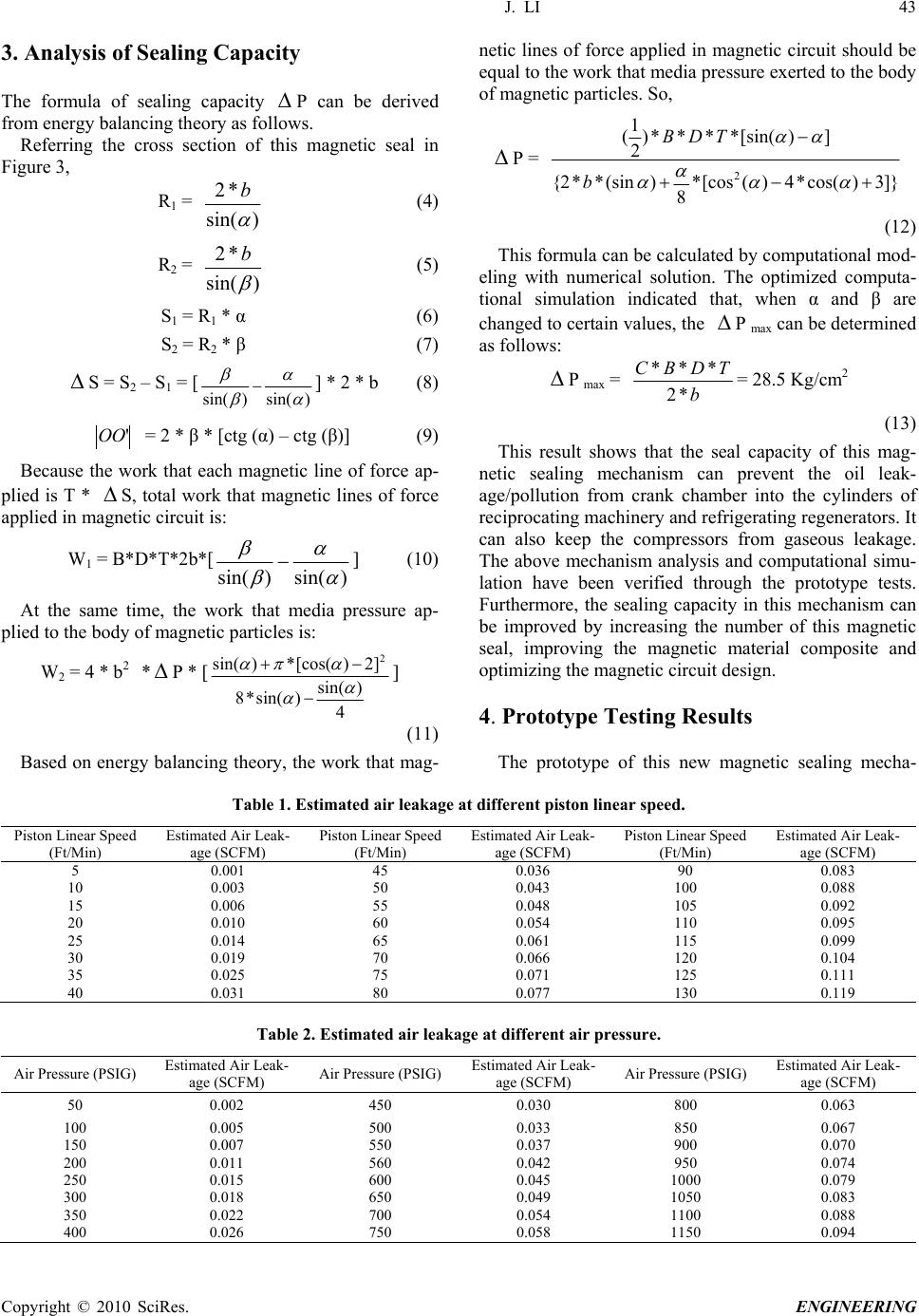 J. LI 43 Copyright © 2010 SciRes. ENGINEERING 3. Analysis of Sealing Capacity netic lines of force applied in magnetic circuit should be equal to the work that media pressure exerted to the body of magnetic particles. So, The formula of sealing capacity P can be derived from energy balancing theory as follows. P = ]}3)cos(*4)([cos* 8 )(sin**2{ ])[sin(****) 2 1 ( 2 b TDB Referring the cross section of this magnetic seal in Figure 3, R1 = )sin( *2 b (4) (12) R2 = )sin( *2 b (5) This formula can be calculated by computational mod- eling with numerical solution. The optimized computa- tional simulation indicated that, when α and β are changed to certain values, the P max can be determined as follows: S1 = R1 * α (6) S2 = R2 * β (7) P max = b TDBC *2 *** = 28.5 Kg/cm2 S = S2 – S1 = [)sin()sin( ] * 2 * b (8) (13) 'OO = 2 * β * [ctg (α) – ctg (β)] (9) This result shows that the seal capacity of this mag- netic sealing mechanism can prevent the oil leak- age/pollution from crank chamber into the cylinders of reciprocating machinery and refrigerating regenerators. It can also keep the compressors from gaseous leakage. The above mechanism analysis and computational simu- lation have been verified through the prototype tests. Furthermore, the sealing capacity in this mechanism can be improved by increasing the number of this magnetic seal, improving the magnetic material composite and optimizing the magnetic circuit design. Because the work that each magnetic line of force ap- plied is T * S, total work that magnetic lines of force applied in magnetic circuit is: W1 = B*D*T*2b*[ )sin()sin( ] (10) At the same time, the work that media pressure ap- plied to the body of magnetic particles is: W2 = 4 * b2 *P * [ 4 )sin( )sin(*8 ]2)[cos(*)sin( 2 ] 4. Prototype Testing Results (11) The prototype of this new magnetic sealing mecha- Based on energy balancing theory, the work that mag- Table 1. Estimated air leakage at different piston linear speed. Piston Linear Speed (Ft/Min) Estimated Air Leak- age (SCFM) Piston Linear Speed (Ft/Min) Estimated Air Leak- age (SCFM) Piston Linear Speed (Ft/Min) Estimated Air Leak- age (SCFM) 5 0.001 45 0.036 90 0.083 10 0.003 50 0.043 100 0.088 15 0.006 55 0.048 105 0.092 20 0.010 60 0.054 110 0.095 25 0.014 65 0.061 115 0.099 30 0.019 70 0.066 120 0.104 35 0.025 75 0.071 125 0.111 40 0.031 80 0.077 130 0.119 Table 2. Estimated air leakage at different air pressure. Air Pressure (PSIG) Estimated Air Leak- age (SCFM) Air Pressure (PSIG)Estimated Air Leak- age (SCFM) Air Pressure (PSIG) Estimated Air Leak- age (SCFM) 50 0.002 450 0.030 800 0.063 100 0.005 500 0.033 850 0.067 150 0.007 550 0.037 900 0.070 200 0.011 560 0.042 950 0.074 250 0.015 600 0.045 1000 0.079 300 0.018 650 0.049 1050 0.083 350 0.022 700 0.054 1100 0.088 400 0.026 750 0.058 1150 0.094  44 J. LI Figure 4. Air leakage vs. piston linear speed. Figure 5. Air leakage vs. air pressure. nism has been tested and the preliminary results are shown in Tables 1 and 2. 5. Computational Simulation Results This new magnetic sealing system has also been simu- lated by computational solution and results are indicated in Figures 4 and 5. Based on the above, the preliminary results from pro- totype testing and computational simulation are closed to each other, and this verifies the creditability and feasibil- ity of this new magnetic sealing mechanism. Copyright © 2010 SciRes. ENGINEERING  J. LI 45 6. Conclusions Today the oil and gaseous media leakages are the tough and difficult engineering problems that affect the recip- rocating machinery function and performance. This new magnetic sealing mechanism has been developed to re- duce the oil and gaseous media leakages in reciprocating machinery. All the theoretical mechanical and magnetic analysis, computational simulation, and prototype tests indicated that this sealing mechanism can significantly decrease the oil and gaseous media leakages in recipro- cating machinery. Its sealing performance is reliable due to the firmly adhesive and strong forces between the magnetic particles and reciprocating pistons/shafts. This seal mechanism is also durable if compared with regular seals including rubber seal, diaphragm seal, corrugated pipe seal because of less frictional force between sur- faces of seal and pistons/shafts in this new sealing mechanism. Moreover, the development of this magnetic sealing mechanism will further contribute to the exploi- tation, popularization, and application of the rich rare- earth elements/materials in today’s modern industrial world. 7 . References [1] H. Quelle, G. González-Jorge, and L. Domarco, “Mag- netic field cancellation on the surface of superconducting rings: Influence on the flux creep,” Cryogenics, Vol. 48 pp. 2–5, 2008. [2] J. E. Hirsch, “The Lorentz force and superconductivity,” Physica A, Vol. 315, pp. 474–476, 2003. [3] H. González-Jorge, B. Liñares, I. Quelle, E. Carballo, and G. Domarco, “Measurement of critical current in super- conducting rings,” Measurement Vol. 40, pp. 378–380. 2007. [4] H. González-Jorge, J. Peleteiro, E. Carballo, L. Romaní, and G. Domarco, “Procedure to induce a persistent cur- rent in superconducting cylinders or rings,” Applied Physica, Vol. 81, pp. 420–421, 2002. [5] H. González-Jorge, J. Peleteiro, E. Carballo, and G. Do- marco, “Inducting technique and trapped field in ring-shaped Superconductors,” Physica, Vol. 433, pp. 132–134, 2005. [6] P. W. Anderson, “Theory of flux creep in hard supercon- ductors,” Physica, Vol. 9, pp. 309–311, 1962. [7] U. Topal, L. Dorosiskii, H. Ozkan, and H. Yabuz, “Effect of thermal neutron irradiation in boron-doped melt- tex- tured YBCO superconductors,” Physica, Vol. 388, pp. 401-403, 2003. [8] L. Shlyk, G. Krabbes, G. Fuchs, K. Nenkov, and B. Schupp, “Flux pinning and magnetic relaxation in melt-processed YBa2Cu3O7-d dopped with Li,” Journal of Applied Physica, Vol. 96, pp. 371–374, 2004. Copyright © 2010 SciRes. ENGINEERING  46 J. LI Nomenclature Ag = cross section area of working gap Bg = density of magnetic flux in working gap Br = density of magnetic flux (BH)max = maximum product of magnetism and energy C = coefficient D = Width of magnetic steel f = coefficient of circuit efficiency H = intensity of magnetic field of magnet steel Hg = intensity of magnetic field in working gap L = length of magnet steel Lg = length of working gap T = intensity of magnetization U0 = magnetic conductivity of vacuum Vg = volume of working gap V = volume of magnet steel B = half length of working gap = magnetic flux Copyright © 2010 SciRes. ENGINEERING |